Up until recently, I did all of my soldering the “old-fashioned” way with my soldering iron. As I began building up boards for complex projects that use a multitude of surface mount components, I started to realize how inefficient that method is. It’s a lot of tedious work to solder each individual SMD component by hand, especially tons of capacitors and resistors. It’s the same repetitive task over and over again: put solder on one of the pads, pick up the component with tweezers, heat up the solder I just put on the pad, put the component into place, optionally push the component down against the PCB while heating the solder, and finally solder the other pad. When you’re building a board that only has a few parts, it’s no big deal. When you’re building a board that has 20 or 30 capacitors and resistors, it can really get boring and slow. It’s definitely doable, but it’s also exhausting.
I investigated other methods of soldering. This research led me to solder paste. The idea is that you put solder paste onto all of the surface mount pads on your PCB. Next, you place the surface mount parts onto the pads. The paste holds the parts in place so you can move the board around without sending components flying all over. When you have all of the parts in place, you heat up the board to melt the solder and activate the flux. Some people use a hot air rework station to do this; I prefer putting the board into a repurposed toaster oven. I’ll explain in more detail later in this post.
Of course, I still use my iron for a lot of stuff I do: through-hole parts, drag soldering fine-pitch ICs, fixing problems, soldering boards that use a small number of SMD components, and probably other situations I’m not thinking of at the moment. I think there’s a point at which it becomes more efficient to use solder paste instead, particularly if you’re building up multiple boards at once. I’m not sure exactly where that “critical point” is, but you develop a feel for it as you gain more experience. If I’m doing a single board with about ten 0805 components, I’d rather do that by hand with an iron. If I’m doing five of them, or a board with 30 0805 components, I’m going to lean toward using solder paste. The main reason for this is the cost of setup time. It takes longer for me to get set up for building boards with solder paste (not to mention cleaning up when I’m finished). So if I’m going to get set up for a solder paste soldering session, I’m going to prefer if I have a lot of soldering work to do to make the setup time worth it.
There are also situations that basically require using solder paste, such as components with leads that are difficult or impossible to reach by hand. For example, many QFN packages have a large ground connection underneath the chip. Some smaller connectors like micro-USB connectors and microSD sockets are also difficult to do by hand. These can probably be done using normal solder and a hot air rework station (or in some cases, careful soldering with a small iron tip), but it’s usually easier for me to just do the whole board with solder paste in that case despite the setup time.
What I’d like to do in this post is share and describe my soldering setup. With the right tools, solder paste can be pretty fun to work with.
Solder paste
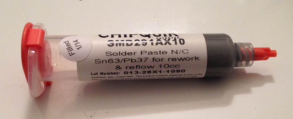 There are a lot of options out there for solder paste. I can’t speak for all the options because I’m relatively new to the market, but I have had good luck with Chip Quik SMD291AX10 paste and Zephpaste. Solder paste typically has a shelf life of 6 months or less. If you refrigerate the paste it will last longer, but I don’t really care to put the paste in the same location as my food. It lasts long enough without refrigeration for me. If your solder paste dries up and quits working, you can always buy more. Keep this in mind when you buy solder paste–only buy as much as you need.
Not only are there a lot of options for the paste, but there are options out there for putting the paste on the board. Perhaps the best method is to have a stencil made. Many PCB fabrication shops can also make stencils you can use for applying solder paste. You secure the stencil over your board, put some paste on the stencil, use a squeegee to spread the paste over the holes in the stencil, lift the stencil up, and you are left with a board that only has solder paste in the places where you want it.
 If you don’t want to have a stencil made, you can also manually apply the paste onto pads by pushing it through the syringe. If you go this route, you will also want to get a variety of dispensing needles that you can attach to the syringe. You can find these on eBay and many suppliers. I got a variety pack from Zephyrtronics (see near the bottom of the link). In addition, if the syringe does not come with a plunger, you will need to pick one up so you have something to push to make the solder paste come out.
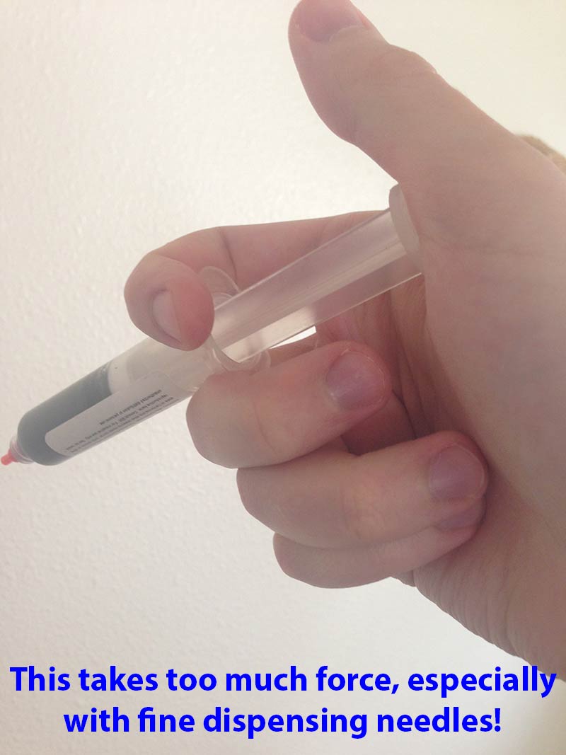
I’m not a big fan of manually dispensing the paste by hand using the syringe. It requires much more force than you might think to push the plunger. I even bought a fancy plunger that is supposed to be more comfortable, but it’s still way too difficult to use. One thing that helps is to cut the needle length down. I use an X-acto knife to cut the needle down so it barely sticks out. You have to be careful because if you push down with too much force while cutting, you’ll squish the needle and it will be bent shut. There are also some tapered plastic tips that are easier to use, but their disadvantage is that it’s easier to accidentally smear the paste when you’re dealing with small pads that are close together.
I found a happy medium between having a stencil made and manually dispensing the paste: a solder paste dispenser! You can attach an air tube to the end of your syringe and use compressed air to push the solder through the syringe. It’s foot-operated so you push a pedal and the paste starts coming out of the needle (you will still need to get the dispensing needles). Because you no longer have to exert force pushing on the syringe plunger, it’s much easier to concentrate on aiming the paste onto the pads.
Solder paste dispenser
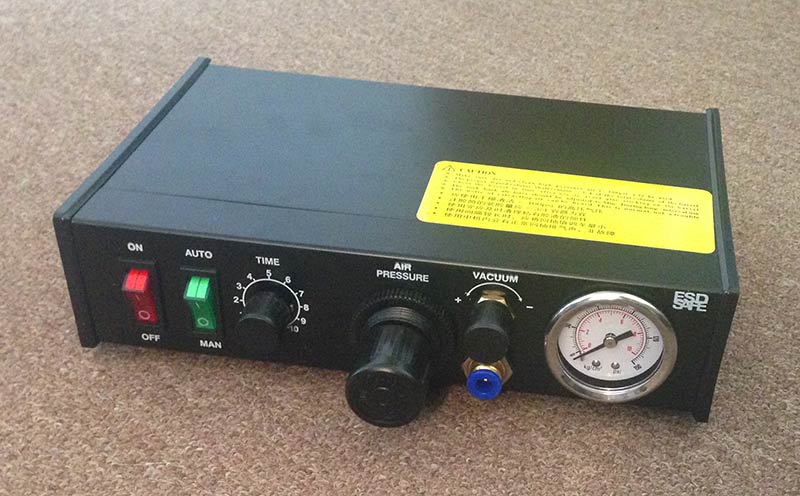 The dispenser I decided to buy was a cheap (~$100) dispenser on eBay. It doesn’t have a model number on it, but it appears to be a “982” dispenser. I’ve seen this model for sale under the names KLT-982A and SP982. The eBay item didn’t specify a part number. I made sure to buy a version that was advertised as a 110V model compatible with the United States; some of the items on eBay only work on 220V power. I also made sure to buy one that operates on 24V DC power internally because I had heard that some of the older versions actually had 110V power going through the foot pedal–that sounds a little risky!
You can operate it using either a foot pedal or a hand switch. It has a manual mode where as long as you’re pushing down on the pedal, air is pushed through. There is also an adjustable auto mode where it will put out timed pulses of air. Ideally you could use this to dispense exact quantities of solder paste. In practice I’ve found that the auto mode works inconsistently, so I just dispense everything in manual mode. Once you get the hang of it, it’s not too bad. Since I’m only using manual mode, the controller is probably overkill and a clever person could put something together on their own with a valve and foot pedal (and pay a lot less money in the process). I’m too lazy to care; the pre-assembled controller is way more convenient and clean than hacking something together.
I did mention earlier that you need compressed air. This adds more stuff you have to learn about. This is actually the main reason I decided to write this post. Before messing with solder paste I knew nothing about air compressors and the different types of connectors you use to hook things up. I had to go research all of this stuff for myself and I’d like to simplify it for anybody else who buys a solder paste dispenser in the future.
Air compressor and fittings
If you’re going to use a solder paste dispenser, you need a source of compressed air, somewhere in the range of 50 psi or so. I didn’t have an air compressor when I got started, so I did some research to decide on something appropriate for my needs. I didn’t want to get the very smallest compressor available, so I went with the Porter-Cable C2002-WK. It goes up to 150 psi and has a 6-gallon tank. It was still pretty reasonably priced. I was glad I picked this one because it is big enough to handle all of my needs. When I’m going to be applying solder paste, I fill up the tank once, set the regulator to 50 psi, unplug it, and shut it off. It will have plenty of air for the rest of the day. The dispenser barely uses any air at all. The compressor is fairly loud when indoor so I don’t like being near it when it fills up. It’s nice that I can turn it on, walk away until it’s done, and then shut it off knowing that it won’t have to fill back up anymore.
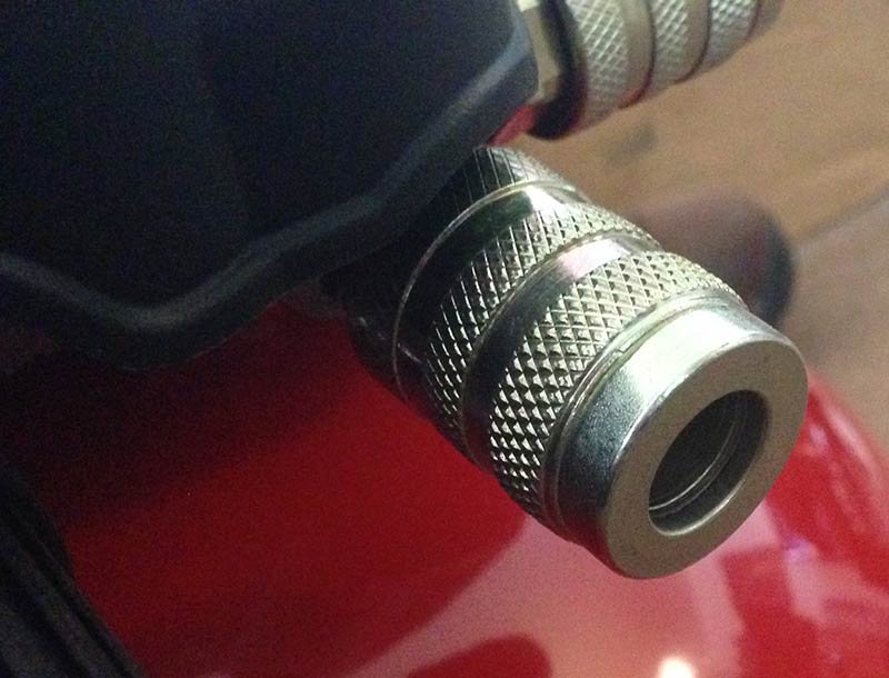
I’m brand new to air compressors, so I’d like to share everything I needed to learn in order to get this system up and running. First of all, the air compressor has this type of connector for hooking something up to it:
It also comes with an air hose with an identical connector. The other end of the hose plugs into the compressor’s connector.
This connector is sometimes called a “quick-connect” or something similar. The idea behind these connectors is that when nothing is plugged into a female connector, air is not allowed to flow. As soon as you plug something in, air is allowed to start moving. To plug it in, you pull back the sleeve on the female connector and push the male connector in. To remove it, you pull back on the sleeve and the male connector pops out. There are many types of quick-connect couplings out there; this one is called an industrial connector.
That explains the air compressor side of things, but what about the receiving end? The connector on the solder paste dispenser is pretty interesting. You see this little blue connector on the back where you feed the air in?
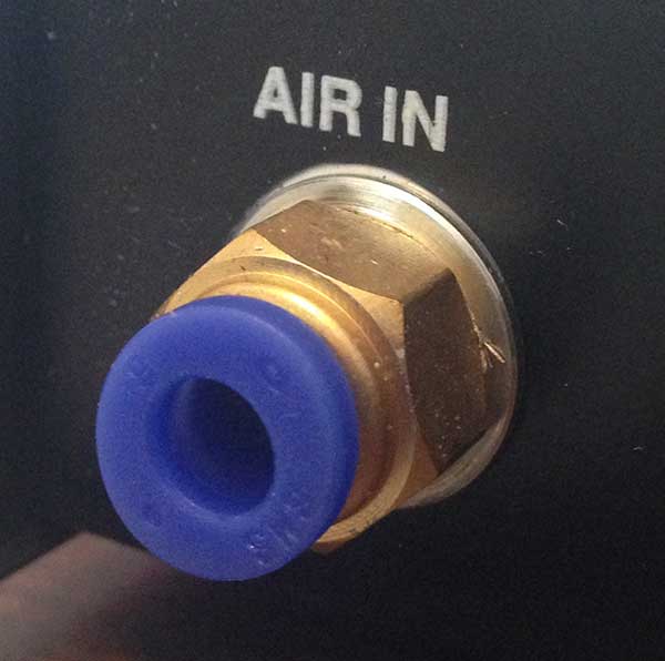
This is what’s called a push-to-connect fitting. You stick an air tube into the connector and it will stay in place. If you try to pull it out it won’t come out. To remove it, you push on the little blue ring that you can see on the connector (it’s kind of like a button). While pushing that blue ring in, you can easily pull the air tube out. It’s really a nifty setup. According to this page, this connector on a similar dispenser accepts tubing with a 6 mm outer diameter. This seems to match what my connector accepts. If you need to get tubing for it, I would definitely recommend to look for 6 mm tubing instead of a similar size in inches just to be safe.
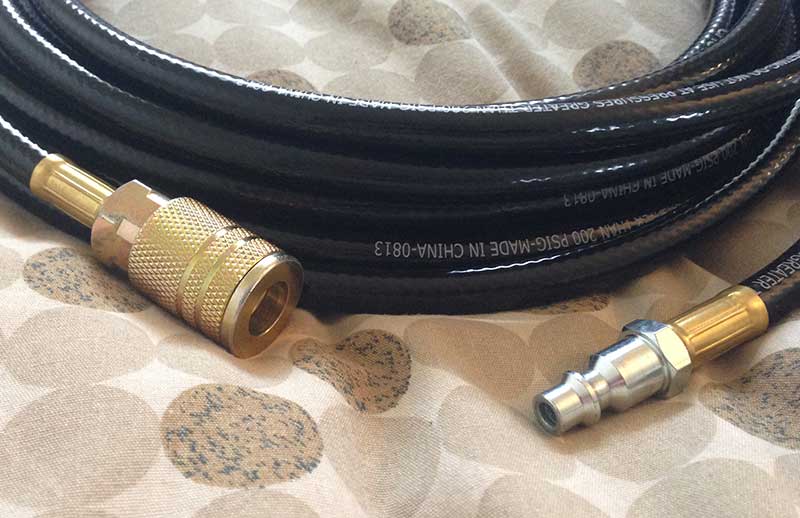
The dispenser comes with an air hose for plugging into this connector. One end is just the bare hose that plugs into this push-to-connect fitting. The other end has a strange quick-connect coupler that seems to baffle many people online:
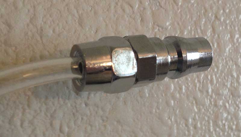
This is not the industrial connector that my air compressor expects. I don’t really think I found a definitive answer for what type of connector this is, although I did find a lot of theories. This link was actually very helpful. It seems that this connector is some kind of Asian connector that is not typically found in the United States. After a ton of Googling, I took a gamble and bought a 30E570 coupler. On eBay this goes for about $27 plus shipping. Since the URL might change, I’m not going to link to it; just search for it. It claims to be a “1/4 inch Asian Hi Flow Interchange” adapter. This adapter provides a female connector that mates to the weird male connector on the air tubing that came with the solder paste dispenser. I don’t know if the connector is an exact match, but it seems to fit and it doesn’t leak, so it’s good enough for me!
The other end of this coupler gives you a 1/4″ female NPT. NPT (national pipe thread) is a standard type of threading commonly found in the United States. With NPT stuff, you screw the male and female connectors together, typically wrapping some teflon tape around the threads to ensure a good connection with no leaks. My compressor came with yet another adapter that converts 1/4″ male NPT to the quick-connect needed for plugging into the compressor, so I was able to screw this adapter onto the 30E570 coupler to make something that could finally hook into the compressor.
If you don’t want to buy the weird Asian Hi-Flow to NPT adapter, there is another option: you can buy an adapter that converts 6 mm outer diameter push-to-connect to 1/4″ NPT. There is a male NPT version or female NPT version of this adapter available. Then you just need some bare 6 mm outer diameter tubing and you can connect the tubing between your adapter and the dispenser. Here’s an example of what I mean if you want to try this option:
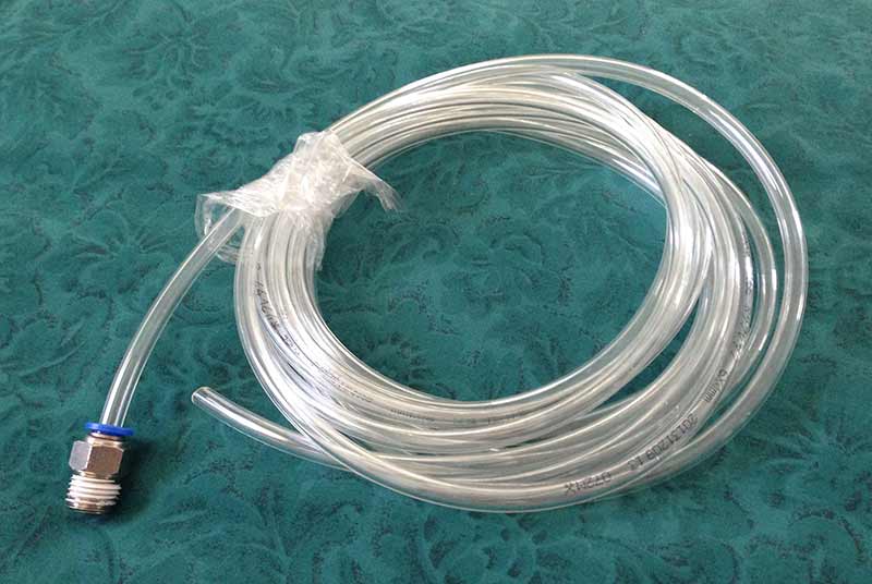
You’ll also need a 1/4″ NPT to quick-connect adapter so you can plug it into the compressor. I went ahead and used the Asian Hi-Flow adapter instead though, as you’ll see below.
Air filter
The solder paste dispenser’s documentation says it needs dry, clean air. Air compressors typically put some moisture and oil into the air, so it’s a good idea to add a filter. As far as I can tell, it’s not a huge problem with smaller compressors, but it’s still a good idea just in case. I bought an Ingersoll Rand F35121-400-VS air filter and put it into the chain of connections. It has 1/4″ female NPT connectors for input and output, so with a 1/4″ NPT male-to-male nipple and the 1/4″ male NPT to quick-connect adapter I mentioned earlier (this kit has a nice variety of connectors and this sealing tape worked great), I was able to assemble this final monstrosity that can hook into my air compressor’s hose:

I read that it’s a good idea to put the filter closer to the dispenser than the compressor, so I hook this assembly into the long hose that came with the compressor to add some distance. Setting up the connection between the compressor and the dispenser was definitely the hardest part to figure out about this whole setup. It would have been nice if either the dispenser had an NPT connection or the included tubing had a standard industrial connector. Either of those two options would have been great. Regardless, it’s not really a concern for me now because I have the required connections. I really hope this information is useful to other people who are considering buying one of these dispensers. This is a huge stumbling block especially for someone like me who is new to pneumatics. I honestly knew nothing about anything I wrote in this section until I researched it online in order to figure out what I needed for this dispenser.
A few more air compressor notes
If you’re going to be a new air compressor owner, I’d like to share a few tidbits. First of all, when you’re done and you release any remaining pressure, it can be extremely loud, especially if you’re indoors. With the tank mostly full, I released the air through the safety valve like the instructions mentioned, and I was very surprised by how loud it was. My ears were bothering me for several days afterward. If you’re going to do that, I would highly recommend earplugs. I prefer to hook up the included air blower tool and release the air through it; it’s much quieter.
After the tank is mostly depressurized, you need to open up the drain valve at the bottom and drain out any liquid. I typically haven’t seen much (if any) moisture come out of my tank when I only fill it up once, but I do see liquid come out if the compressor has to run a lot when I’m using it for something other than solder paste. You should always check to make sure. If you don’t drain the tank it could develop rust inside and that would be a very bad thing.
Connecting to a solder paste syringe
We have covered hooking the dispenser up to the compressor, but what about the solder paste syringe? The air output of the dispenser uses another push-to-connect fitting with the same size as the air input (6 mm outer diameter). The dispenser came with three 30cc syringes and an adapter to connect the dispenser up to a 30cc syringe. It’s basically tubing connected to a cap you can put on the syringe. The cap has an O-ring to keep the syringe sealed tightly.
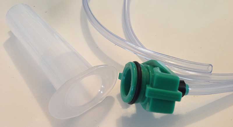
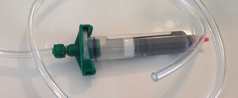
The solder paste I bought came in a 10cc syringe, so I didn’t have an appropriate adapter to hook it up. I found some 10cc syringe adapters on eBay and bought them (this adapter on Amazon should work too). The adapters I bought looked exactly the same as the 30cc adapter, except they were smaller and had a green plastic connector instead of bare tubing at the end. I messed around with the green connector and discovered it is a very bad idea to push it directly into a push-to-fit connector. Instead, you should cut off the green connector and just use the bare tubing. Luckily, the one I found seemed to fit perfectly even though the tubing diameter wasn’t specified. The adapter fits tightly onto the solder paste syringe and then twists to lock in place:
Dispenser needles
As I mentioned earlier, I bought a variety pack of needles. After experimenting with them, I have settled on two favorites: 21-gauge (about 0.22″ diameter) and 23-gauge (about 0.16″ diameter). The 21-gauge tip works well for most purposes. For really fine-pitch stuff such as 0402 capacitors and resistors, the 23-gauge tip is able to dispense a smaller amount of paste. Both of these sizes would take a lot of force to do by hand.
When I first put a needle onto the solder paste syringe, it takes a while for the paste to make its way through. I usually have to push down on the pedal non-stop for 15 seconds or so before the paste starts coming out. Cutting the needle shorter than its original length helps with this problem.
I’ve read that these dispensing needles are not reusable, but in my experience you can reuse them if you clean them out. When I’m finished using them, I put them on an empty syringe and hook the empty syringe up to my dispenser. Then I blow out the rest of the solder paste until only air is coming out of the needle. You can also fill the syringe with water to do a better cleaning job if you want.
Dispensing the paste
I think I’ve shared everything you need to know in order to get everything hooked up. Once it’s all hooked up and you’ve filled up the air compressor, you’re ready to dispense paste. I usually set the air compressor’s pressure regulator to about 60 psi. I’ve never needed more pressure than that. You don’t want to go higher than what the dispenser’s documentation says it can take (100 psi on mine). You can play around with the regulator on the solder paste dispenser to find your sweet spot. I usually set it to about 50 psi or so. You don’t want to go too high, but it has to be high enough to get the solder paste through the thin dispensing needle. You may find that a higher pressure makes the paste come out faster. It’s all up to your experimentation.
Like I said earlier, I don’t trust the auto mode on the dispenser. It’s a really cool idea, but what I’ve noticed is sometimes the needle clogs up and stops dispensing for a while. There are other times when the paste temporarily starts coming out quicker than usual as well. Because both of those situations happen fairly often, I’ve opted to stick with manual mode. When I press down on the foot pedal, the air starts pushing paste out. When I release the foot pedal, the air stops pushing. It may sound annoying to handle it manually, but it actually works pretty well.
I generally put a dab of paste on each SMT pad. When I’m dealing with multiple small pads, such as a QFP or PLCC package, I put a line of solder paste across the pads. This is another good application of the manual mode of the dispenser. You can see an example of solder paste across multiple pads in the picture below (this is one of my Mac ROM SIMM programmer PCBs after I have dispensed paste onto the pads).
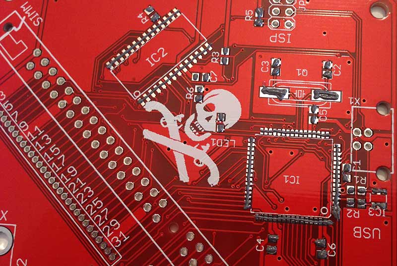
Putting the line of paste across multiple pads is pretty tough. You have to use an appropriate gauge of needle and you have to get just the right amount of paste. If you don’t use enough, some of the chip’s pins will not get enough solder. If you use too much, you’ll end up with pins shorted together. Shorting is especially a problem with fine-pitch components: 0.5 mm and less.
On the pads for the QFP device in the picture above, I got my paste a little thin near the top of the right side and too thick on the bottom of the right side. I luckily didn’t end up with a short on the part where it was too thick, but I didn’t end up with quite enough solder on the part where it was too thin. You’ll see what I mean on the finished board later on.
When I do a board with 0.5-mm-pitch components, I actually solder those components ahead of time with a soldering iron using drag soldering. I’m just better at drag soldering than paste dispensing. After I have the difficult components placed, then I dispense paste for handling the easier components. I would guess that solder paste stencils would work a lot better for getting just the right amount of paste for fine-pitch parts though. Definitely consider having a stencil made if you’re going to be building PCBs in high volumes.
Placing the components
The solder paste holds the parts in place after I drop them onto the PCB. There are many ways to place the parts. The most common way is probably to grab components with fine tweezers and drop them into place. If you’re only placing a few parts, that’s probably the easiest way to do it. At some point, I started realizing that placing a ton of components was annoying, so I searched for a better way to do it. What I’m about to describe is the best solution I came up with. Credit goes to this YouTube video for inspiring me.
The video talks about a vacuum pickup tool. The idea is you have a little pen you hold in your hand. By either pushing a foot pedal or covering a hole on the pen with your finger, you get vacuum suction that is strong enough to pick up a part. The guy in the video recommends something that is foot-operated because otherwise it’s hard to move your finger off the hole without moving the pen, thus jerking the part around that you’re trying to drop. I wholeheartedly agree, but I couldn’t find anything affordable that was foot-operated.
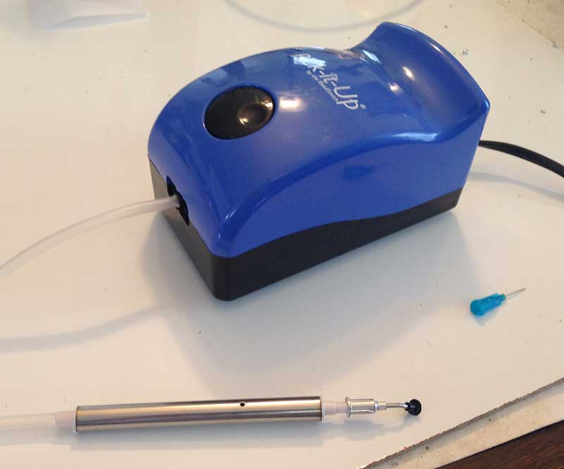 I ended up finding something that isn’t even designed with electronics in mind. It’s called the BeadSmith Pick-It-Up. It’s available from many retailers online (including Amazon). It’s actually meant for people who are doing arts and crafts to assist them with picking up small beads and stones. I’ve found that it works great for my application too! I had a concern about ESD safety since it’s not designed for electronics, but I haven’t had any problems yet.
It comes with a single tip that’s too large for picking up 0805 components, but should be OK for picking up larger things. It also has a little rubber attachment that you can put on the tip to help you get good suction on things with a large surface area. In the picture on the left, I actually have a separate tip attached that came with a different (junky) squeezable vacuum pickup tool I bought. It’s terrible, but the tip it came with is nice. You will also see in the picture that I use one of my solder paste syringe tips for picking fine components up. That blue tip is a 25-gauge needle and it works great for picking up 0805 parts. Just make sure you don’t accidentally suck up any solder paste! 0402 components are so small that I don’t think I could pick them up very reliably. I stick with tweezers for parts that small.
There is a dial on the top that you use to adjust the strength of the suction. You just have to experiment with it until you find what works. Like I said earlier, you put your finger over the hole on the pen, and then the pen should magically pick up the part. I’ve found that when you move the part onto the solder paste, the solder paste will actually grab it with enough force to snatch it from the vacuum tool. This is actually helpful because you don’t have to worry about moving your finger off of the hole when you’re ready to release the part.
I’d like to share one other related piece of advice from the video I linked above. Before I got this vacuum tool, I would take resistors/capacitors I bought from Digi-Key or Mouser or whatever out of the “cut tape” that they typically come in and dump them into little containers. With a vacuum tool, though, it’s actually beneficial to leave the components in the cut tape. With some double-sided sticky tape, you can adhere the cut tape to your workbench. Now every component will be in the exact same orientation with the correct side up. It really speeds up the process of populating the components on your board(s). The downside is that the cut tape takes up a lot of space for storage.
Here’s what the board above looked like after I placed all of the parts:
Cooking the boards
Finally, after you have placed the components, you need some way to heat the solder paste up so it permanently solders everything to the PCB. I suppose you could do it by hand with a soldering iron, but that would be messy and you would move the parts while trying to heat the solder. You could also do it with a hot air rework station. I’ve heard that some people like to use a skillet. I prefer sticking the board into a cheapo toaster oven that I dedicated for soldering. Yeah, smoke and nasty fumes come out. Don’t cook your food in it. Preferably do this outside so the fumes don’t permeate your indoor air.
Using a regular old toaster oven instead of a specialized reflow oven presents a few challenges. Most importantly, you need some way of monitoring the temperature inside the oven to know when it’s time to quit heating. You also have to watch the oven and manually try to follow a heating profile because there’s no controller to do that for you automatically. There are temperature controller kits out there that you can use to modify a toaster oven and turn it into an automatic reflow oven. That would be nice, but it’s overkill for my needs.
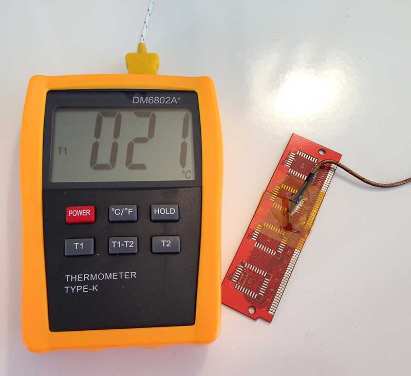
To monitor the temperature, I bought a thermometer and thermocouples. The model I bought was a DM6802A+. It’s a no-name brand but it does the job. It came with two K-type thermocouples, one of which I use for soldering. You’ll see in the picture that it’s discolored, probably due to being cooked combined with the nasty crap that comes out when the solder melts and the flux activates. Anyway, I used Kapton tape (which is safe to use with high temperatures) to attach the probe to a spare PCB. I did this to try to make sure I am getting a good idea of the temperature of an actual PCB in the oven.
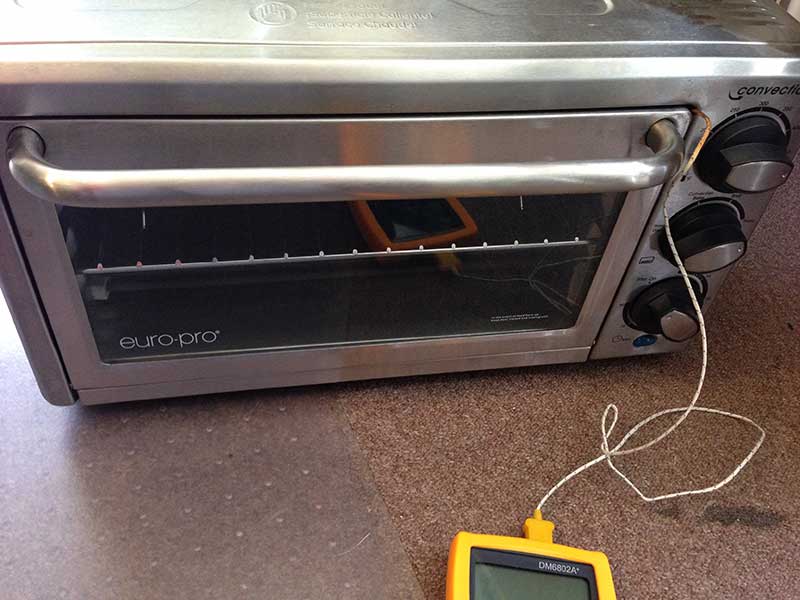
The oven I use is a Euro-Pro TO36 convection oven, which as far as I can tell is no longer available. I’m sure you can find a cheap toaster oven somewhere if you want one. Anyway, despite the fact that this model is a convection oven, I’ve found that I have to turn the convection feature off or else the temperature has trouble getting to where I want it (around 220-230° C for solder that has lead, or 250-260° C for lead-free solder). I just use the toast function which doesn’t turn the convection fan on. It has both upper and lower heating elements, although I haven’t figured out which elements turn on in each mode–the documentation that came with the oven doesn’t do a good job of explaining it. Ideally you’d want the convection fan and both the upper and lower elements turned on. You could definitely set it up correctly if you opened it up, stripped out the original timing circuitry, and put in an automatic reflow controller instead. This oven gets the job done for me without a controller and without convection, so I haven’t had the need.
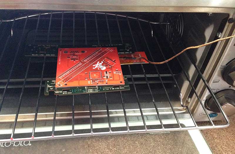
I use some spare PCBs to support the PCB I’ll actually be cooking, and of course I stick the thermocouple probe with its PCB in there too. In a real-world scenario, the red PCB I have on top is the populated PCB that I would be cooking. I would also remove the baking pan that you can see underneath; I just forgot to remove it when I took this picture.
When I close the oven, the thermocouple probe sticks out and connects to the thermometer:
The insulation on the thermocouple wire is good to about 260° C; if I needed to go higher than that, I would need to get a better probe that can withstand higher temperatures.
After everything is in place, I set up the oven controls. I turn the temperature knob all the way up to the maximum temperature. I put the timer knob in the “stay on” position so it doesn’t count down. As I mentioned before, I put it into toast mode. Finally, I plug it into the wall and watch as the temperature increases. I just want to repeat: I do this process outside on a sunny day. The solder paste and flux both make nasty fumes that I don’t want to smell inside.
When the temperature reaches about 10° C below my target temperature, I turn the temperature knob all the way down. It definitely overshoots, so you want to turn it down early. It’s a feel you develop over time. I believe I have discovered through my experience that the amount of overshoot can change based on the temperature outside. Once it has reached my target soldering temperature, I unplug the oven from the wall. It should do a decent job of maintaining the temperature for a while. I try to keep it at my target high temperature for 30 seconds or so. When I’m ready for the temperature to decrease, I carefully open the oven (the solder will be molten and a bump could dislodge components on the PCB) and turn on a fan that I point into it.
This is where the fumes really start coming out of the oven, so I usually walk away and wait for it to cool down. As the “Will It Blend?” guy would say, “solder smoke, don’t breathe this!” When the thermocouple is reading 80° C or so, it has probably cooled down enough to pull the baked PCB out and inspect it:
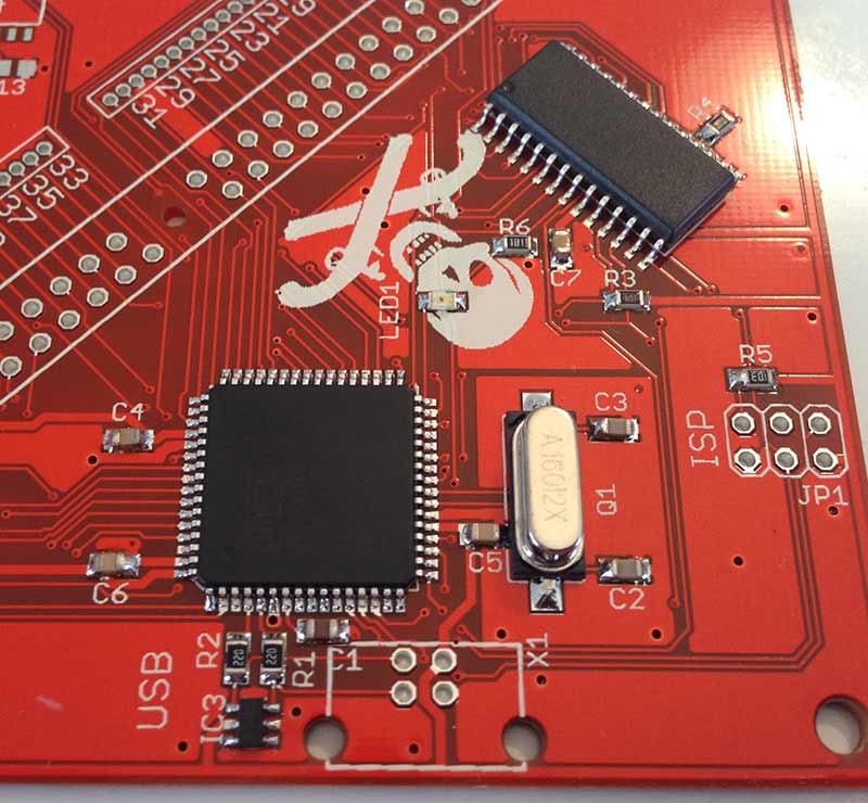
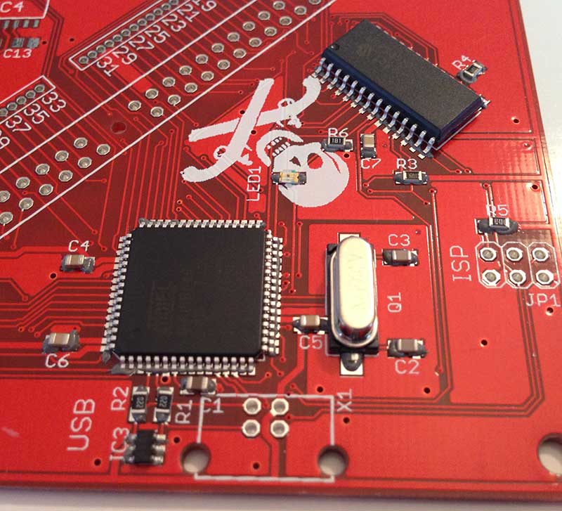
As you may be able to see, a few of the pins in the bottom row of the QFP device (an Atmel AT90USB646 AVR microcontroller, in case you’re curious) didn’t get quite enough solder. That corresponds to places where the line of solder paste was too thin. The leftmost pin in that bottom row has too much solder; that’s the place where I put too much paste. I was lucky enough to not get any bridged pins, but I definitely saw that happen on some of the other boards I built in the same batch. I had to do some touchups with my iron to fix the bridges and add extra solder in places where it looked like there wasn’t enough.
All in all, the solder joints look pretty nice. I built ten of these boards in one sitting and I’m positive that I saved a ton of time by using solder paste instead of soldering each 0805 component by hand. It took some time to bake all of the boards, but I was able to spend that time standing and walking around instead of sitting in front of my soldering workbench. However, this board has a small enough number of components that a single board would probably be easier to just do by hand.
By the way, I have successfully baked two boards at a time in my oven. It still seemed to work fine. I’d be afraid to try too many at once because I don’t know how well the heat spreads throughout the oven. Convection is supposed to help heat the entire oven uniformly, but I have convection turned off.
Cleaning up
When I’m all finished, it takes some time cleaning up and tearing down. Before letting the air out of my compressor, I put the dispensing needles onto an empty syringe and blow any remaining solder paste out of them so I can reuse them. If I really wanted to be frugal, I’d start doing this before I was finished dispensing paste to avoid wasting the paste that’s left in the needle.
Next, I let out the air. I disconnect my weird filter monstrosity from the air line and hook up the little blow gun that came with my compressor. I use this to blow most of the air out. When most of it is gone, I open up the drain valve on the bottom to let any liquid out.
After everything is depressurized, I open up my air filter and make sure to empty out anything in it. I haven’t found anything in my filter yet, and I think this is because the compressor doesn’t typically put much moisture into the air unless you’re using a lot of air and it keeps having to run.
I put away all of the air hoses and junk for connecting the compressor to the dispenser, and that’s about it!
Conclusion
Solder paste is pretty cool. Stencils are probably the way to go, but if you don’t want to use stencils because you do small quantities of many boards, a dispenser works well too. It has a bit of a barrier to entry especially if you don’t know about air compressors, but once you get the hang of it, it’s actually pretty easy. An air compressor is a good tool to have around the house anyway, so keep that in mind if you don’t have one.
Questions? Comments? Suggestions? Please let me know in the comments area below. I hope this information helps someone! Please be careful if you decide to get into this hobby. High pressures and high temperatures can both be very dangerous. Wear eye protection when you’re working with this stuff. Use common sense–don’t stick your hand into the hot oven and burn yourself, don’t blow air into your face, and make sure all air connections are nice and tight. I’m not responsible if you hurt yourself, burn your house down, or whatever else you could possibly imagine; I’m just sharing the process I use when I build PCBs.