In my last post, I wrote about how I had figured out how the Macintosh IIci’s synthesized startup sound works. I talked about how I replaced the ROM chips on the motherboard with sockets and disassembled the ROM code. I shared a video showing how I customized it to play the first few notes from the Super Mario Bros song. At the very end of it, I talked about how it would be awesome to figure out how to play a sampled sound at boot time, which would allow me to play any sound I wanted, limited by space available in the ROM. I didn’t feel very optimistic about getting that done, but after a ton of reading, experimentation, and frustration, I have figured it out, and my IIci now plays a sampled startup sound when it boots up. I’d like to share how I did it, as well as provide instructions on how to patch your own IIci’s startup sound with the sound of your choosing.
Before I start, I’d like to thank the people in the 68k Mac Liberation Army forums for the help and encouragement, and also the people who coded the MESS emulator for leaving a very handy register reference for the Apple Sound Chip in their source code. Without any of the aforementioned people, I would never have been able to get this far in my hacking!
Here’s are some videos, followed by how I did it and how you can do it. I decided to inject one of the sampled startup sounds from the LC/Performa series into my IIci:
And here is the sampled startup sound from the 5200/5300/6200/6300 series Macs:
How I did it
To begin, I disassembled an LC III ROM dump. The LC III is one of the oldest Macs that has a sampled startup chime. Its sound chip is not quite the same as the IIci’s, but the way it plays its sampled sounds at boot time gave me a few clues. To write sampled sounds to the Apple Sound Chip, you basically just keep writing samples, one at a time, as long as there is room in the chip. You determine whether there’s room in the chip or not by reading a status register.
So based on how the LC III did it, I wrote a program to test playing a sound by talking directly to the sound chip on my IIci. It failed miserably for two reasons:
- The bits of the FIFO status register in the sound chip act slightly differently on the LC III compared to the IIci
- When I’m booted into the Mac operating system, there are interrupts looking at the status of the sound chip. An interrupt can grab the FIFO status before I get a chance to see it, and then I’m stuck waiting in an infinite loop for a bit to change, even though it already changed long ago.
No biggie though! First of all, I decided to forget about the FIFO status register completely, and instead I made my program write samples blindly to the chip, adding a pause occasionally to give the chip some time to play the samples and clear space in its FIFO. I messed around with my delays, and I eventually was able to get it to mostly work. By mostly, I mean sometimes it would make some crackly sounds while playing the sound I wanted it to play. I figured this was because interrupts sometimes made my delays longer than they should have been, causing the FIFO to empty out for a short time. My main goal was accomplished though: I knew how to tell the chip to play sounds.
The delay code was lame, though. It makes more sense to listen to what the chip is telling me, rather than guess the status of the chip based on time delays. To solve problem #2, I disabled interrupts during my program. This helped immensely because it prevented the operating system from talking to the sound chip behind my back. Next, I started playing with the status bits to see when they come on and turn off. It was here that I discovered problem #1: The IIci’s sound chip doesn’t behave the same way the LC III’s code implies its sound chip behaves.
The LC III’s code always waits for one of the FIFO status bits to be “1” before it writes a sample to the chip–even the very first sample. The MESS source code says this bit is a “FIFO half empty” status bit. On the LC III, it looks like this bit is 1 any time the FIFO is anywhere between completely empty and half empty. If it’s more than half full, the bit is zero. On the IIci, though, this bit stays at zero, and only becomes 1 once you have filled the FIFO more than half full and it has dropped back down to being only half full by playing enough samples. Plus, once you read the bit, it goes back to 0 until the FIFO has filled more than half full again (and dropped back down to half full after that, which sets the bit at 1 again). This explained why my first attempt failed — an interrupt probably read the status bit’s 1 value (bringing it back to 0 in the process) and I was stuck waiting to see it and never did.
Once it’s finished writing all the samples to the chip, the LC III’s code waits for another status bit to be 1 before continuing on. I’m guessing that this other bit acts as a “FIFO is completely empty” bit, so it’s allowing the code to wait until the FIFO has totally drained out. I don’t know for sure, but that would make the most sense based on what the code is doing. On the IIci, though, according to my tests, this bit is zero until the FIFO is completely full. Then it becomes 1 until you read it, and it resets back to zero immediately.
Based on this information, I decided on an algorithm to use with the IIci to play sampled sounds driven totally by the two status bits:
- Check the “FIFO is full” bit.
- If the FIFO is not full (the bit was 0), write the next sample to the chip and start over again at the top.
- If the “FIFO full” bit was 1, then wait until the “FIFO is half empty” bit comes on, then write the next sample to the chip and start over again at the top.
So the algorithm starts with the FIFO completely empty, fills it completely up, then waits for it to become half empty again, fills it completely up, waits until it’s half empty, fills it up, and so on, until it’s done.
I couldn’t find a way to determine that the FIFO was completely empty, though–so I may be cutting off the end of the sound. I’m not sure about that yet. I don’t notice it, but it’s possible that the sound I’m playing has some silence at the end of it anyway.
So after getting it working in a simple Mac program, I injected the code into the free space in the IIci’s ROM and patched the ROM to jump to my routine instead of the normal startup chime. After a monumental screwup where I accidentally commented out a single line that caused the whole thing to fail and had me puzzled for hours, I got it to work on my second try!
A couple of days later I tried another sound. The 5200/5300/6200/6300 startup chime is actually sampled at 11.127 KHz, which is half the Apple Sound Chip’s standard sample rate. So to play it, I changed my code slightly to write each sample into the sound chip twice, doubling the effective sample rate to 22.254 KHz. This also lets me use a sound twice as long!
So that’s my background info on how I did it. Now…I’m sure you’re chomping at the bit to do it yourself, right?
How you can do it
You need:
- A working Mac IIci
- Some soldering and desoldering skills
- Four 32-pin 0.1″ pitch DIP sockets
- Four pin-compatible EEPROMs (I used the Greenliant GLS29EE010)
- An image of your Mac IIci’s ROM — read it from the chips after removing them or read it from the Mac before you tear it apart. (Do NOT ask me for ROM images – I’m not interested in infringing on Apple’s copyright)
- An EEPROM burner compatible with the EEPROMs you choose and a computer that it can talk with — most likely it will be a Windows-based computer with a parallel port.
- The ROM patches I will provide below
- A hex editing utility to stick the patches where they belong (I used HxD)
- A tool to recalculate the ROM’s checksum after your modification. Ben Boldt’s Mac ROM Checksum verifier will help you figure out what the checksum should be (nice work Ben!) — note: if you run this program on Windows, change the code so that it opens the files in binary mode. Otherwise it won’t work because it will do weird stuff with bytes that happen to be carriage returns and line feeds.
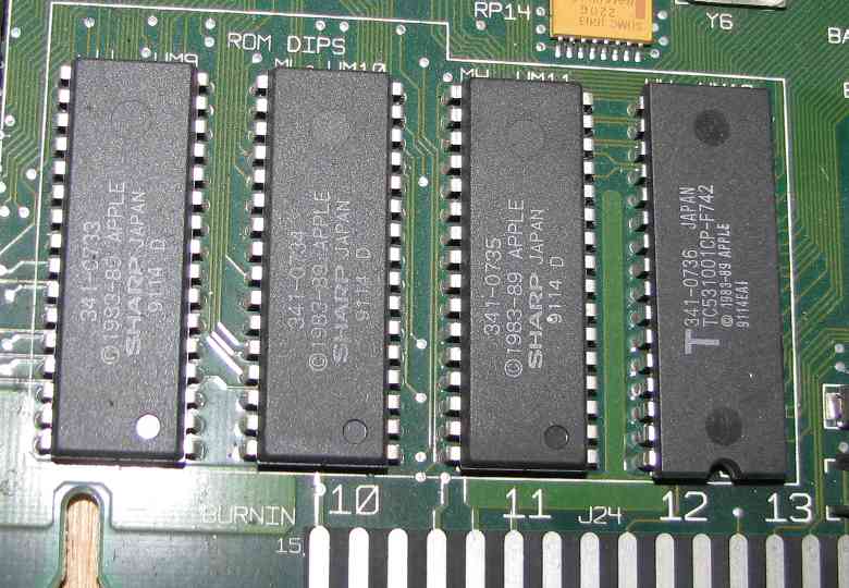
- A tool to split the ROM file into four interleaved segments for burning. I made one for .NET that also does the checksumming but I don’t have time to upload it yet…if you don’t want to wait, make a suitable tool yourself! 🙂 See my previous post for info on how the ROM chips are interleaved.
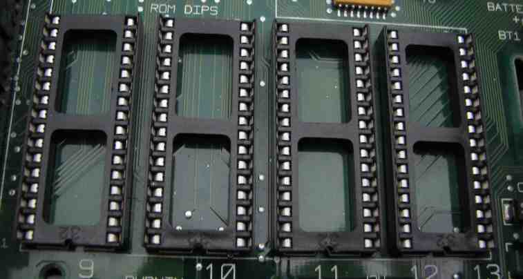
All right! As far as hardware goes, desolder the old ROMs and remember where each one goes. Solder sockets in their place and put the original ROMs into the sockets to make sure that it still boots OK. Each EEPROM will have at least one extra pin that was not connected on the IIci’s original ROM. It will need to be connected to something and not left floating. See the datasheet of your chip to determine what it should be connected to for “read mode”. In the case of the GLS29EE010, it is a pin right next to VCC that is used for programming (the pin is called WE#), and in read mode it is supposed to be pulled high. How convenient! On the bottom of the motherboard, you can blob solder between these two pins to connect them and it should work well–at least for the GLS29EE010!
Now, read the ROM files onto your computer (or use the image you read from the Mac before tearing it apart and split it into 4 interleaved files). Burn the four ROM segments onto your EEPROMs, stick them in place of the original ROMs, and make sure the IIci still works. This will verify that your EEPROM burner and the hardware modifications are working correctly.
From this point on, it’s all software. First of all, here is the source code I used to generate this binary blob of sound-playing goodness (if you want to compile my code to make changes, you will need a 68k version of GNU binutils):
Sampled startup chime source code for Mac IIci
Here is the final assembled 140-byte binary generated from the source code:
Sampled startup chime binary ready for injection into Mac IIci ROM
You will need to append your own sound to the end of this binary blob. It should be in raw 8-bit unsigned format with a 22254 Hz sample rate. Audacity should be able to produce a file in that format for you [File–>Export–>Other uncompressed files–>Options–>RAW (header-less)–>Unsigned 8-bit PCM], and it should also be able to take a sound sampled at a different rate and convert it to 22254 Hz [Tracks–>Resample]. After the end of my binary blob, append the length of the sound (in number of samples) as a four-byte big-endian integer. Then append the raw 8-bit unsigned file you generated containing your sound. I decided to skip Apple’s sound resource format or AIFF or WAV or anything like that because it would do nothing except complicate the sound playing code.
Stick your combined blob into your ROM image (overwriting the old bytes so the file does not grow in size) starting at an offset of 0x51D70 (you should see an Apple copyright notice repeated over and over again along with other stuff). It can’t be longer than about 35 kilobytes, though, or it will start overwriting other stuff in the ROM. Make sure that some of Apple’s copyright notice is still visible and you’ll be fine! 🙂 If you don’t yet have a single ROM image because you read the ROM from the original chips, you need to combine them into a single file first — remember, they are interleaved!
Next, we need to patch the ROM image to jump to our newly-injected code instead of the standard startup chime code. It’s a simple matter of changing the four bytes starting at the offset 0x435D2. In your ROM image they should be:
FF FC 3A 82
You need to change them to:
00 00 E7 A0
Also, if you plan on using this patched IIci ROM in an SE/30 (and I’m guessing also a IIx/IIcx, but I can’t confirm that), you also need to change the four bytes starting at the offset 0x4122C. They should already be:
FF FC 5E 28
Change them to:
00 01 0B 46
Finally, recalculate the checksum using Ben’s tool I linked to above, split the ROM image into four segments, burn the segments to EEPROM, stick them in your IIci, and power it on! If all goes well, you will hear your awesome new startup sound. Otherwise, you probably have some troubleshooting to do 🙂
You know what’s really cool about this hack? I ended up using a Mac, Windows, and Linux together to do the job. Just the way I like it!
