A couple of weeks ago I found a really good deal on a Socket AM4 motherboard that supports the newest AMD Ryzen CPUs. The motherboard is an ASRock A520M/ac. It’s a very basic motherboard which doesn’t appear to be sold by any of the usual retailers anymore, but I couldn’t pass up on the deal, especially with the potential it had for being a fun learning project.

The reason I got such a good deal on it was because it was sold in non-working condition, but the seller and I both had a pretty good hunch about what was wrong. The seller said that they had bought it as an open box unit, but couldn’t get it to POST. However, they had only tried CPUs in it that were not compatible with the original BIOS version. I decided to have some fun and see if that was indeed the only problem. I didn’t have an older CPU available to easily test that theory. I did have a new Ryzen 7 5700G, which is only supported by BIOS revision P1.60 or newer.

Typically, there are several simple options for using a newer CPU with a motherboard that needs a BIOS update in order to support it:

  1. Borrow an older CPU just long enough to install an updated BIOS. AMD has a program for handling this if you don’t have an easier way to borrow one. I don’t know if this is a valid option if I’m not the original buyer of the motherboard. AMD’s documentation requirements in order to participate seem pretty stringent based on the linked instructions.
  2. Use the “USB BIOS Flashback” feature to update the motherboard’s BIOS even without a CPU installed. This particular motherboard doesn’t support that option.
  3. Send it back to the retailer or manufacturer to update it for you. I have no idea which retailers/manufacturers might do this. There’s no way that Amazon, for example, would provide this service.

It’s possible that ASRock would have tried to help me out if I had asked, but I decided to turn this into a fun personal challenge instead: upgrade the BIOS on my own without using an older CPU.

Read the rest of this entry

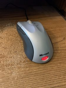
My favorite mouse is my Microsoft IntelliMouse Explorer 4.0. I bought my first one back in 2009. I love how the scroll wheel smoothly spins. I’ve never had another mouse like it. I want to keep using it forever and ever.

Read the rest of this entry

Last week, my main Linux computer died. It has an ancient Intel DX58SO motherboard from 2009 with an LGA 1366 CPU socket. A couple of years ago, I replaced its original Core i7-920 processor with a Core i7-980 from eBay. Considering its age, it’s actually a pretty powerful computer: six 3.33 GHz cores.

Anyway, here’s what happened. I was working, and just as I was about to join a meeting, I heard all of the fans in the computer stop spinning. The power LED remained on, but other than that, the machine looked like it was powered off. I tried power cycling it, but it was completely dead. After power cycling, the power LED wouldn’t turn on either.

Read the rest of this entry

, , , , , , ,

Long story short: Dell recently released a bad BIOS update (3.9.0) for the Inspiron 3650 that seemingly bricked people’s computers. Luckily somebody discovered an easy fix you can do yourself by changing a jumper on the motherboard. If you’re interested in hearing how I fixed it in a much more convoluted way before this info about the jumper was available, keep on reading.

Read the rest of this entry

A while ago, I put 16 GB of RAM into one of my computers. The computer is using a Foxconn P55MX motherboard with a Core i5 750. It’s old and could probably be replaced, but it still works for what I need.

Here’s the interesting part. This motherboard doesn’t officially support 16 GB of RAM. The specs on the page I linked indicate that it supports a maximum of 8 GB. It only has 2 slots, so I had a suspicion that 8 GB sticks just weren’t as common back when this motherboard first came out. I decided to try anyway. In a lot of cases, motherboards do support more RAM than the manufacturer officially claims to support.

I made sure the BIOS was completely updated (version 946F1P06) and put in my two 8 gig sticks. Then, I booted it up into my Ubuntu 16.04 install and everything worked perfectly. I decided that my theory about the motherboard actually supporting more RAM than the documentation claimed was correct and forgot about it. I enjoyed having all the extra RAM to work with and was happy that my gamble paid off.

Then, a few months later, I tried to boot into Windows 10. I mostly use this computer in Linux. I only occasionally need to boot into Windows to check something out. That’s when the fun really started.

Read the rest of this entry

At work, I was trying to restore a Lenovo IdeaPad Z510 back to the factory default configuration after Ubuntu Linux had been installed on it. I wanted to restore it back to the factory default Windows 8.1 scheme. I noticed that Lenovo had a “One-Key Recovery” (OKR) option, so I decided to try it. I pressed the NOVO button and chose the system recovery option. When I tried to run system recovery, it gave me this error message:

The program cannot restore the system partition because its structure is incorrect. You may have to recreate the partition to continue.

I wasn’t the one who set the laptop up originally, but I was pretty sure that since Ubuntu was installed, it had changed something about the partition layout and broken something. So I booted into an Ubuntu Live USB stick and used GParted to check it out. Sure enough, a few extra partitions had been created for ext4 and swap. It appeared that the main Windows partition had been shrunk, and the extra Linux partitions had been created in the space made available. I deleted the extra Linux partitions and resized the main Windows partition to fill up the available space.

Unfortunately, that still didn’t fix it. Maybe it would in some people’s cases, but something was still wrong with the partition layout. I started digging into the recovery partitions on the laptop’s hard drive and found a file that contained info about the partition layout. It was on the partition called PBR_DRV, and the path to it was OKRBackup\Factory\Info.ini. This file contained info about the location, size, and options for each partition.

I was able to use the information in this file, combined with the “gdisk” command while booted into an Ubuntu Live USB, to fix everything. It turned out that all of my partitions were the correct size, but the “Attributes” from this file didn’t match — several of the partitions were missing the “don’t automount” flag.  I was able to use gdisk to set that flag on partitions that needed it in the expert menu. Also, for some reason, the MSR partition had been deleted, so I was able to recreate it (I created it as a new unformatted partition and set the label in GParted) and set the proper “Id” and “Type” GUID values using gdisk as well. I don’t know if Ubuntu deleted it, or if the person who installed Ubuntu manually deleted it.

For some reason, the partitions were numbered incorrectly after I did all of this, so I was able to use the “sort” function in gdisk to number the partitions properly afterward.

After I confirmed that the labels, locations, sizes, “Id”/”Type” GUIDs, and attributes all matched between Info.ini and the actual disk, I saved my changes to the partition table and tried running the system recovery. This did the trick and everything worked fine!

I didn’t write down paths or anything while I was doing this, and I had to do some Googling to find the names again, so I might be slightly off on some of the filenames. But what I described is pretty much what I did. For future reference, I did write down the following information about the partitions, in case anybody might find this useful:

  • sda1: WINRE_DRV
    • Start sector = 2048
    • End sector = 2050047
    • Size = 1000 MB
  • sda2: SYSTEM_DRV
    • Start sector = 2050048
    • End sector = 2582527
    • Size = 260 MB
  • sda3: LRS_ESP
    • Start sector = 2582528
    • End sector = 4630527
    • Size = 1000 MB
  • sda4: MSR
    • Start sector = 4630528
    • End sector = 4892671
    • Size = 128 MB
  • sda5: Windows8_OS
    • Start sector = 4892672
    • End sector = 1874599935
    • Size = 891.55 GB
  • sda6: LENOVO
    • Start sector = 1874599936
    • End sector = 1927028735
    • Size = 25 GB
  • sda7: PBR_DRV
    • Start sector = 1927028736
    • End sector = 1953523711
    • Size = 12.63 GB

I recently ran into a problem upgrading a computer from Windows 7 to Windows 10. I received an error message with the following error code: 0x800703ed

It turns out this system was a dual-boot Linux and Windows system. I was actually booting to a different hard drive which had GRUB installed, and then GRUB was booting to my Windows drive. I fixed the problem by switching my BIOS boot order to boot directly to the drive with Windows 7 installed and then repeated the update process. This resulted in a successful Windows 10 upgrade. After the upgrade was complete I was able to change my BIOS boot order back to the way it was before, and now everything works fine.

I have a homebuilt computer with an Antec Sonata III case and an Intel DX58SO motherboard. I really, really like both the case and the motherboard, but I’ve been struggling with a sound problem in the computer for two years now. It never bothered me enough to think about fixing it until last week, but I finally fixed it tonight and would like to share my story.

The problem goes as follows:

I use the front panel headphone jack a lot on my computer. The sound coming out of that jack was always fine until I plugged a high-speed USB device into one of the two front panel USB ports. As soon as I did that, I would always hear weird “beeps” or “screeches” in my headphones as USB data was being transferred. The problem was especially noticeable with things like external USB flash drives, my iPhone, and my AVR ISP programmer, but not with lower-speed devices like USB gamepads. It only affected the combination of the front headphones and the front USB ports — devices plugged into the rear USB ports would not affect the headphones, and devices plugged into the front USB ports did not affect the rear speaker jack.

In some ways, it was actually kind of cool to be able to hear USB data transfers, but it would get annoying when I was trying to listen to music. I did a lot of Googling about this problem, and it turns out that it’s a common problem with some of Antec’s cases (and cases by other manufacturers too). The connector you plug into your motherboard for the front USB ports has a ground pin on it. The connector you plug into your motherboard for the front audio ports also has a ground pin on it. So your motherboard provides a ground for each of these connectors. The problem is that the front port assembly on my case connected the ground pins for the USB ports and the audio ports together on its end. This created a ground loop. My understanding is that because the USB and audio connectors provide their own separate grounds through different wires, they should not be connected together at the front panel because if the two grounds differ slightly in voltage (which they can, because wires and PCB traces do have a [small] resistance), current will flow between them. This current flow manifests itself as weird sounds on my headphone jack. (I’m really not an electrical engineering expert, so if I’m incorrect or lacking in my explanation, someone please let me know in the comments below).

Here are some forum/blog postings by other people who encountered this same problem on other case models:

I was able to verify this by using my multimeter in “continuity test” mode. After disconnecting all the case’s wires to the motherboard, I tested the continuity between the high definition audio (HDA) connector’s ground pin and the USB connector’s ground pin. It showed continuity, so that proved that the USB and audio connectors’ grounds were hooked together somewhere inside the front panel module.

Before I did any of these diagnostics, I was writing back and forth with Antec’s customer support. I must say, Antec has excellent customer service. The people I’ve dealt with are friendly and knowledgeable. Antec customer support told me that they have this problem fixed in a newer version of the front port assembly. Meanwhile, I was waiting for it to arrive, so I decided to play with my existing front port module to see if I could fix it myself, knowing that even if I failed, a new one was on the way. With nothing to lose, why not go for it?

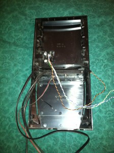
First, I took the air filter out (it slides out of the bottom of the front of the case). Next, I removed the front of the case. This was slightly tricky — I removed all 5.25″ devices (just my DVD burner in this case) and the external 3.5″ drive bay. With those out of the way I was able to pull off the front of the case by releasing the 6 tabs holding it on (3 on each side of the case — top, middle, and bottom). The front panel module also had a wire screwed to the chassis which I had to disconnect (interestingly, this wire is only attached to the front panel eSATA port — it has no connection whatsoever to the audio or USB ports — good thing because that would probably cause another ground loop!)

Here’s the front of the case, completely removed:
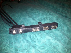
The front port assembly was attached to the front of the case by 3 screws — I removed these and then it was free to go:
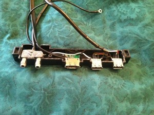
Unfortunately, the front port assembly is sealed–it’s glued together or something along those lines. It’s not held together with screws or anything like that, so it’s kind of a pain to open up. It was no match for my X-Acto knife though! I was able to cut around where I could see the two plastic halves meet, and with the help of a small screwdriver, pried it apart. Amazingly, the two halves of the plastic casing stayed intact! The culprit immediately jumped out at me: there was a white wire coming out of the sealed audio assembly and soldered to the shield of one of the USB ports. I checked it with my continuity tester to be sure, but I already knew it had to be that wire, because it was the only wire that connected the USB ports to the audio ports. (This picture was taken after I had hacked it, but I tried to recreate what it looked like at first)
I grabbed my soldering iron and desoldered the white wire from the USB port:
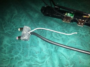
Before doing anything else, I plugged the USB ports and audio jacks back into the motherboard, booted it up, and tested to see if the interference was still there. It was GONE! In fact, I was able to make the interference reappear by momentarily touching the white wire back to the USB port. My multimeter confirmed that disconnecting the white wire had indeed separated the audio and USB grounds from each other. I ended up cutting off most of the white wire and covering the remaining stub with electrical tape just to be safe. Somehow, even after my hack job with the X-Acto knife, the two halves of the plastic case for the front port assembly snapped back together (and stayed that way), so I didn’t have to reseal it. I put the case back together, and the audio output from my headphone jack is perfect now. I can’t hear any interference at all anymore, even if I turn my sound up all the way and plug in both my AVR programmer and my iPhone to the front USB ports.

I wish I had fixed that one a long time ago!

Epilogue:

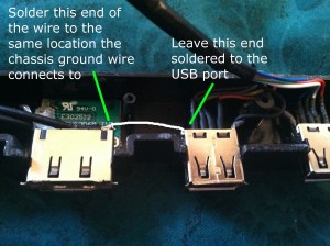
The replacement front port assembly from Antec arrived, and it also fixes the sound problem. If you don’t want to hack apart your front assembly, get ahold of Antec customer support. They are great! I would definitely recommend getting a replacement assembly from Antec instead of hacking apart your existing one. For anyone interested, I checked out the new assembly with my multimeter, and it correctly has the USB and audio grounds separated now. The new revision also makes another change I thought I’d mention: the USB ports are also grounded to the chassis now (only the eSATA port was before — now both USB ports and the eSATA port are). So if you insist on doing it yourself, it might be wise to take that white wire you cut and use it to connect the USB and eSATA grounds together, so they will all be grounded to the chassis.

The easiest way would probably be to leave the white wire soldered to the USB port, cut it off on the audio port end, shorten the wire, and solder the other end to where the chassis ground wire connects to the little eSATA PCB. Here’s an illustration of what I mean: