This is the final post in my blog series about getting my Chumby 8 from 2011 working on a modern 6.x Linux kernel, as opposed to the stock 2.6.28 kernel it came with. Here are links to all of the previous articles where I went into detail about the various obstacles I had to overcome: 1, 2, 3, 4, 5, 6, 7, 8, 9, 10, 11, and 12. I guess we’ll finish it off with lucky number 13.
It has been over two years since that fateful day when I started trying to get a newer U-Boot working on my Chumby to kick off this whole process! I haven’t been working nonstop on the Chumby this whole time though. I completed most of my work on this project by early 2023, and since then I’ve just been trying to catch up on writing these posts and also fixing little issues as they’ve come up. It’ll probably never be fully completed though. I will likely run into various problems in the future as new kernel versions come out and things inevitably break.
I’m not going to cover U-Boot as part of this. If you’re curious about that, check out the first post in the series. Most of the work I did was in Linux. Let’s start by looking at everything I accomplished in the kernel, grouped by subsystem. We’ll see the commits that are in the mainline kernel versus the commits that I haven’t submitted upstream for whatever reason. I’m also linking to all of the original patches on lore.kernel.org in case you want to see the related code review and discussion.
Way back in part 2 of this series, I first got my Chumby 8 booting into a newer Linux kernel. (Here are links to parts 1, 2, 3, 4, 5, 6, 7, 8, 9, 10, and 11 if you want to read the rest of the saga). At that point early on in the project, I had to get the UART driver working. I didn’t spend much time talking about the UART in that post, but it actually gave me a small challenge that I recently had to revisit. I thought it would be fun to tell the full story of the UART struggles I ran into.
When I was first figuring out how to configure my new kernel, I noticed that the pxa168.dtsi file included in the mainline kernel already had the UARTs added. They each had two compatible strings, in order of priority: mrvl,mmp-uart and intel,xscale-uart. This makes sense because Intel’s XScale architecture was used for many things including the PXA series. Then the PXA series was sold to Marvell in 2006, who later designed the PXA16x processor used in the Chumby 8.
Searching through the kernel sources, there were actually three drivers that reference the mrvl,mmp-uart compatible string: 8250_pxa, 8250_of, and the deprecated pxa driver. I originally tried out 8250_pxa, but I ran into a problem with it. During large transmits, for example when typing “dmesg” after the kernel booted, it would drop a ton of characters. Here’s a small excerpt of a modern recreation of the issue in a newer kernel:
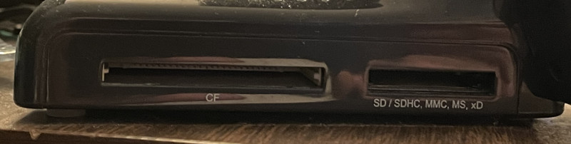
As my Chumby 8 kernel upgrade project neared the finish line (read parts 1, 2, 3, 4, 5, 6, 7, 8, 9, and 10 first if you want), I noticed something subtly annoying. The built-in SD/CF card reader was allocating its own dummy block device (/dev/sda) even if no cards were inserted.
scsi 0:0:0:0: Direct-Access Multi Flash Reader 1.00 PQ: 0 ANSI: 0
sd 0:0:0:0: [sda] Media removed, stopped polling
sd 0:0:0:0: [sda] Attached SCSI removable disk

# ls /sys/class/block/
mmcblk0    mmcblk0p1  mmcblk0p2  mmcblk0p3  sda
This may seem nitpicky, but I really didn’t want that empty sda device hanging around. Apparently neither did the original Chumby team, because the old 2.6.28 kernel had a workaround to avoid it. Let’s look at the relevant portion of the schematics. There are two sockets, and the SD/MMC/MS/xD socket has a bunch of pins for different card types, so the card reader takes up two whole pages. Let’s focus on just the SD/MMC pins. You can imagine that the CF/MS/xD sections look very similar:
I’m going to start this post off with the obligatory list of links to the previous parts in the series if you’re new here and are interested in seeing the full story: 1, 2, 3, 4, 5, 6, 7, 8, and 9. This is the tale of how I upgraded my Chumby 8 to run a modern Linux kernel.
I only had some minor things on my list to figure out before I could call my kernel upgrade good enough to be finished. The most important remaining thing was the real-time clock, or RTC. I noticed that whenever I rebooted the Chumby, it always started out with the date set to the Unix epoch in 1970:
Would it really be this simple? Did I just need to enable the RTC in my device tree file, make sure the kernel driver was enabled, and then be done with it? I had already experienced similar success with other PXA168 peripherals. So I tried it out.
If you’re new to this series, I’ve been documenting the process I went through upgrading my old PXA166-based Chumby 8’s 2.6.28 Linux kernel to a modern 6.x version. Here are links to parts 1, 2, 3, 4, 5, 6, 7, and 8. At this point in the project, all of the main hardware peripherals were working great. I noticed something odd when running top though. The CPU usage was always really high, and it wasn’t obvious why.
After getting many of the PXA16x peripherals working in modern Linux kernels during my Chumby 8 kernel upgrade saga (here are links to parts 1, 2, 3, 4, 5, 6, and 7), I really felt like I was starting to reach the finish line. The display was working well enough to play low-resolution videos, I had basic 2D acceleration up and running, the touchscreen was operational, and Wi-Fi worked flawlessly. Audio was the only major component left to tackle. The Chumby 8 has built-in speakers, a headphone jack, and a microphone.
The Linux sound subsystem is something I had exactly zero experience with prior to this project, so it felt very intimidating. It took me a while to get familiar with it. The relevant project is Advanced Linux Sound Architecture (ALSA) and in particular, the ALSA System on Chip (ASoC) layer is where most of my work would be for this project.
Before digging in too deep, I needed to look at the Chumby 8 schematics and figure out what I would be dealing with. With no prior audio experience to lean on, I wasn’t sure what to expect. Let’s take a look at the relevant section of the schematic:
After getting the PWM backlight working in my last post (here are links to parts 1, 2, 3, 4, 5, and 6), there was only one piece remaining for having a fully functional display in my Chumby 8: the touchscreen controller. The display output worked perfectly fine but I couldn’t detect presses on it.
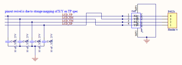
The Chumby 8 and Insignia Infocast 8 have a 4-wire resistive touchscreen:
These aren’t so common anymore — it seems like almost everything is capacitive touch nowadays. I wasn’t familiar with the theory of operation behind resistive touchscreens until I wrote this post. Basically there are two transparent resistive layers. One layer goes left and right and the other goes up and down. When you press the touchscreen they connect together. You can calculate the X and Y positions where the layers meet by driving a voltage across one layer and then measuring the voltage of the other layer. Here’s a nice document that does a great job of explaining it in detail.
In the previous post in this series (here are links to parts 1, 2, 3, 4, and 5), I really got the Chumby to start looking like a Chumby. The display was alive! But getting the LCD controller working was really only one puzzle piece when it came to the display. The backlight needed more work so that I could control the brightness, and the touchscreen controller is a completely nonstandard design that is specific to the Chumby.
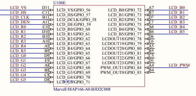
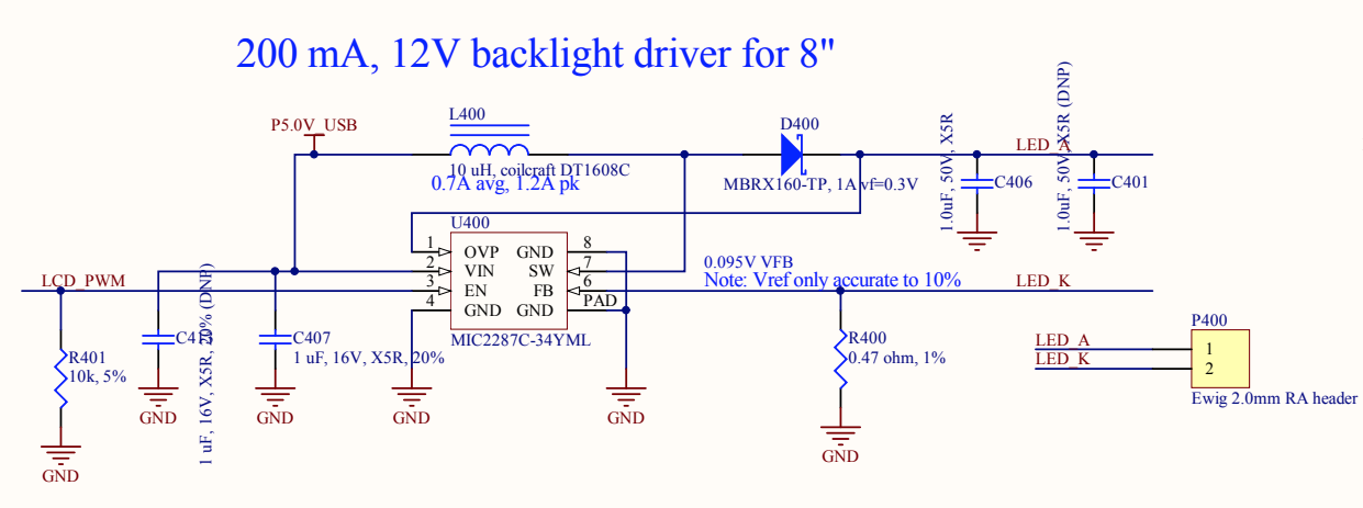
Let’s start with the backlight. This should be pretty straightforward, right? Looking at the schematics, the backlight control is connected to GPIO_84 (also known as PWM_OUT1) on ball A4 of the PXA166. I already knew that I could turn the backlight on full blast by using this pin as a normal GPIO pin and driving it high. That’s what I did in the previous post in order to quickly get it working.
At this point in my Chumby kernel upgrade project (parts 1, 2, 3, and 4 here), I had made a ton of progress but there wasn’t really much to show for it because I didn’t have the LCD working. Even though I had put a ton of work into the project, the display was still black. I knew it was time to get it working.
I started out with U-Boot. As a very basic overview of the LCD controller in the PXA168, basically you just set aside some of your RAM for a framebuffer, copy image data into it, tell the controller the format and address of the framebuffer, set up the clocking and timing, and turn it on. Then it just handles everything in the background for you.
The steps I listed above are overly simplified — there is more stuff going on with the PXA168’s display controller. But it’s enough to get a splash screen working in U-Boot. I booted into the old kernel and dumped the LCD registers using devmem. Here’s an example of this process. The LCD_SPU_DMA_CTRL0 register contains a bunch of format configuration bits for the framebuffer, such as which bits are red/green/blue. It’s at offset 0x190 in the LCD controller, and the LCD controller is located at an offset of 0xD420B000, so I could dump the 32-bit register value with this command:
devmem 0xD420B190 32
This resulted in a printout of the value of the register:
For the next post in my series about upgrading my Chumby 8’s Linux kernel (here are links to parts 1, 2, and 3), I thought I’d look at what was involved in getting the reboot and poweroff commands working properly. I noticed pretty early during the development process that they didn’t work, which was pretty annoying.
The system is going down NOW!
Sent SIGTERM to all processes
Sent SIGKILL to all processes
Requesting system reboot
[   46.457580] reboot: Restarting system
[   47.458947] Reboot failed -- System halted
This meant that in order to restart the Chumby, I had to physically press a button to power it off and again to power it back on. As you can imagine, this got old really fast during development. For that reason it was one of the earliest things that I got working.
I actually implemented it in U-Boot first, but I thought the Linux side of it would be more fun to share. If you want to see what was involved on the U-Boot side, see this commit from my fork of U-Boot.