The last couple of electronics repairs I’ve written about on this blog were both quite involved. Fixing stuff doesn’t always involve crazy rabbit holes though! Here’s a quicker fix that I recently performed.
Fitting in with my recent trend of repairing video capture/camera devices, this time I found a non-working NZXT Signal 4K30 HDMI capture device on eBay. The description of the item was: Tested and the unit powers on, but is not detected by NZXT Cam software. Unable to test further due to this.
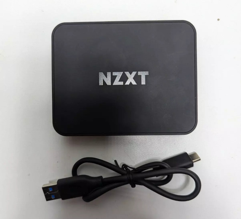
When I received it, I replicated exactly what the listing said. The white light on the front turned on, but then nothing happened. No USB device was detected by my computer at all. Opening it up, I was able to get an idea of the overall architecture. Someone else has also torn this device down, so I didn’t have to start completely from scratch.
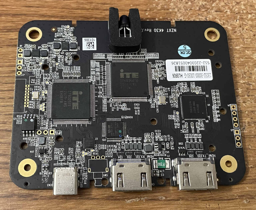
Here’s a summary of the main components:
- ITE IT9325TE Digital Video to USB 3.0 Converter
- I believe this IC pretty much performs the same duties as the Cypress chip from my previous Elgato HD60 S escapades. It takes the captured video and sends it over USB. However, this chip is dedicated specifically for video rather a general-purpose USB 3.0 device controller. That’s a nice advantage — no CPLD necessary.
- ITE IT68050TE HDMI receiver
- I wasn’t able to find this exact chip model on ITE’s site, but it’s likely similar to the IT68051TE, which is a dual-port HDMI receiver IC. I would guess that only one of its two input ports is being used. It will take the incoming HDMI signal and turn it into parallel video data to send to the IT9325.
- CH6001FN HDMI splitter
- This IC was harder to find detailed info about, but it appears to be a 2:1 HDMI splitter IC. I don’t know for sure, but I would guess it’s probably being used to split the incoming HDMI signal. One output goes to the HDMI receiver IC, and the other goes to the passthrough output HDMI port.
- Interestingly, the other linked teardown has an ITE IT6663FN instead of CH6001FN. I’m wondering if they’re really just the same part with different markings. Some of the results on Google refer to the CH6001FN as being an ITE chip. It makes sense too — the other marking codes on my chip are really similar to the markings on the other teardown’s chip. Maybe ITE bought the company that originally made this IC or something.
- MindMotion MM32L073 Cortex-M0 MCU
- I’m guessing this is the microcontroller that is in charge of configuring, controlling, and reading the status of all of the ICs on this board (using I2C).
- eEver/Etron EJ179W USB Type-C CC+MUX controller
- I couldn’t find this exact part number on eEver or Etron’s site, but Etron’s site does refer to the EJ179x as a USB Type-C CC+MUX controller. I believe what this does is route the high-speed USB 3.0 signals from a USB C connector properly so it works regardless of which way the USB-C cable is plugged in.
There’s also an 8 MB Macronix SPI flash chip onboard, but spoiler alert: I didn’t have to mess with it at all!
When I’m first diagnosing something like this, I like to look at easy stuff — make sure nothing is getting hot and the voltages all seem good. It seems like that’s a really helpful way to narrow down a lot of possibilities.
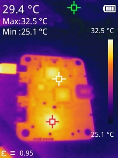
You could see the chips warming up but nothing was getting crazy hot. It all seemed pretty normal. 32.5 degrees Celsius is nothing. Next, I tried to identify the power supplies and make sure they were good. To accomplish this, I looked for small chips nearby inductors. This got a little tricky because I couldn’t find much info from the markings on the ICs, but I figured I could probe the various decoupling capacitors near the video ICs as well as the inductors to see if the voltage rails were working.
I don’t love probing tiny chips when powered on if I can avoid it, but I was able to see 3.3V on the SPI flash chip’s VCC pin, so I knew at least one power rail was working. Before moving onto looking at other chips, I decided to think about things I could safely check with no power applied using my multimeter’s continuity mode.
Looking closer at the inductors, I noticed that one of them seemed like it had a weird mark on it like it had been hit. The others didn’t have this appearance.
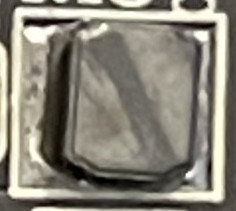
When I measured resistance across it, there was continuity, so it seemed okay. This led me to look at all of the other inductors (why not?) and that’s when I discovered that one of them (the one closest to the USB-C port) didn’t have continuity.
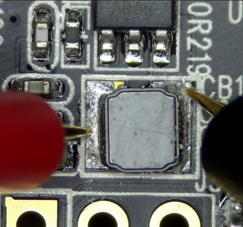
That’s weird. I should always see low resistance across an inductor, but my multimeter was reading “OL” when probing across it. I also noticed the soldering looked a little shoddy. The component wasn’t centered in place, and some of the left pad still had its gold plating visible. Confession: I’ve definitely soldered pads like that by hand. This is different though. I wouldn’t expect a board professionally assembled with solder paste to look like that. It seemed like the solder didn’t get a chance to fully flow.
To be honest, the soldering on this board in general didn’t look the greatest. There were a few other solder joints that looked iffy, but they were connected okay. I poked and prodded, but I couldn’t get anything to register continuity on this inductor. Just to make sure I wasn’t going crazy, I probed the voltage at both sides while it was powered on. One side had 5V and the other side had 0. Yep, there was definitely something wrong. So I removed it and wicked up all the solder.
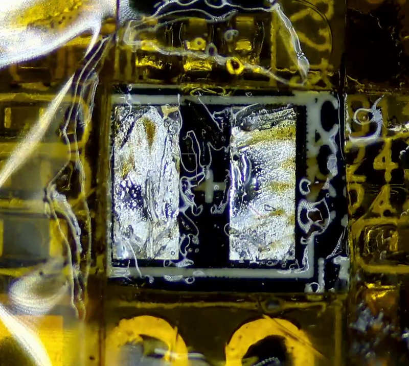
Then came the moment of truth. I probed the inductor directly:
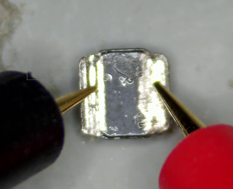
Beep! Continuity! So there was no problem with the inductor itself. There was just a problem with how it was soldered down to the board. I breathed a sigh of relief. I didn’t want to go on a wild goose chase for replacement inductors. I don’t currently own a meter capable of measuring inductance, so I’m not sure how I would have determined a replacement to use. It didn’t have any markings. Maybe I could have identified the nearby IC and looked at its example schematic. Oh well, I’ll worry about that down the road for another repair.
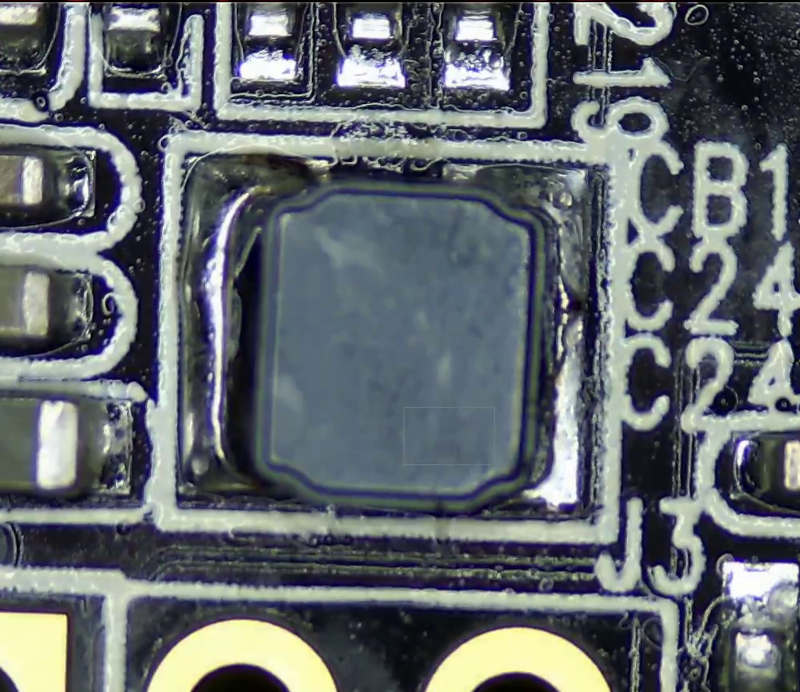
There wasn’t enough room to get my iron tip in there, so I had no choice but to use my hot air station to solder it into place. After cleaning up the flux residue, it looked pretty nice. I probably did put a little too much solder on the left pad, but oh well:
I anxiously plugged the device back into my Linux machine while monitoring the kernel output, and here’s what I saw:
usb 2-2: new SuperSpeed USB device number 3 using xhci_hcd
usb 2-2: LPM exit latency is zeroed, disabling LPM.
usb 2-2: config 1 has an invalid interface number: 7 but max is 4
usb 2-2: config 1 has no interface number 4
usb 2-2: New USB device found, idVendor=1e71, idProduct=2700, bcdDevice= 1.00
usb 2-2: New USB device strings: Mfr=1, Product=2, SerialNumber=3
usb 2-2: Product: NZXT Signal 4K30 Video
usb 2-2: Manufacturer: NZXT
usb 2-2: SerialNumber: 906C012030401826
uvcvideo 2-2:1.1: Unknown video format 30313050-0000-0010-8000-00aa00389b71
usb 2-2: Found UVC 1.10 device NZXT Signal 4K30 Video (1e71:2700)
hid-generic 0003:1E71:2700.0006: hiddev0,hidraw0: USB HID v1.11 Device [NZXT NZXT Signal 4K30 Video] on usb-0000:01:00.0-2/input7
Very promising! That inductor was definitely what was preventing it from showing up as a USB device.

I did run into some problems getting it to work in Linux, but I think I can chalk it up to issues with OBS. It works fine with qv4l2. This capture device is a little flakier than the others I’ve tested, especially in Linux. It seems to work well in Windows. I did find one 720p60 HDMI source that it doesn’t like — the captured video shows up as pink and green. I saw some others on Reddit complaining about a similar issue, but I don’t think there’s anything actually physically wrong. I’m guessing it’s some kind of NZXT firmware bug involving RGB vs YUV, because all other HDMI sources I’ve tested with it work fine (even at 720p60), and all of my other capture devices handle that HDMI source without issues.
Either way, this thing can capture 4K30 video, the retail price is $129.99, and I only paid a fraction of that. I’ll call it a big win! It’s nice to perform an easy repair for a change. I will admit, though, that it involved some luck in stumbling upon the bad solder joint very quickly.


no comments