There have been some past rumblings on the internet about a capacitor being installed backwards in Apple’s Macintosh LC III. The LC III was a “pizza box” Mac model produced from early 1993 to early 1994, mainly targeted at the education market. It also manifested as various consumer Performa models: the 450, 460, 466, and 467. Clearly, Apple never initiated a huge recall of the LC III, so I think there is some skepticism in the community about this whole issue. Let’s look at the situation in more detail and understand the circuit. Did Apple actually make a mistake?
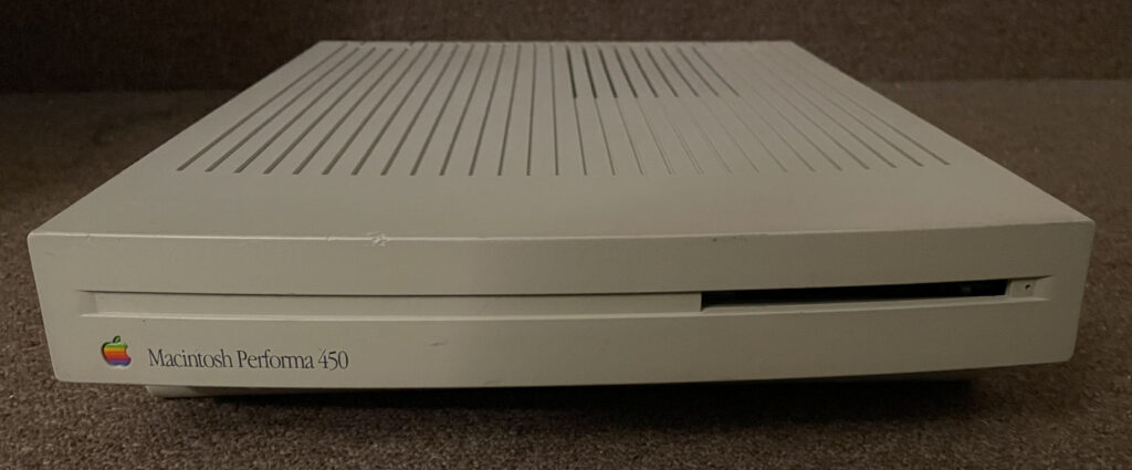
I participated in the discussion thread at the first link over a decade ago, but I never had a machine to look at with my own eyes until now. I recently bought a Performa 450 complete with its original leaky capacitors, and I have several other machines in the same form factor. Let’s check everything out!
Here’s the affected section of the board before I removed the original capacitors. You can see that all three of these caps (C19, C21, and C22) have their negative side pointing upward, matching the PCB silkscreen that has the + sign at the bottom.
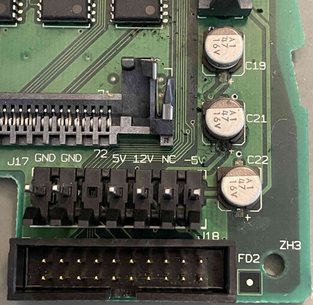
If the miscellaneous gunk and ugly appearance of the solder joints in this picture isn’t a warning sign that you should replace the SMD electrolytic capacitors in any classic Mac from the ’90s at this point, I don’t know what is! Let’s take a closer look at the circuit after I removed them and cleaned everything up a bit.
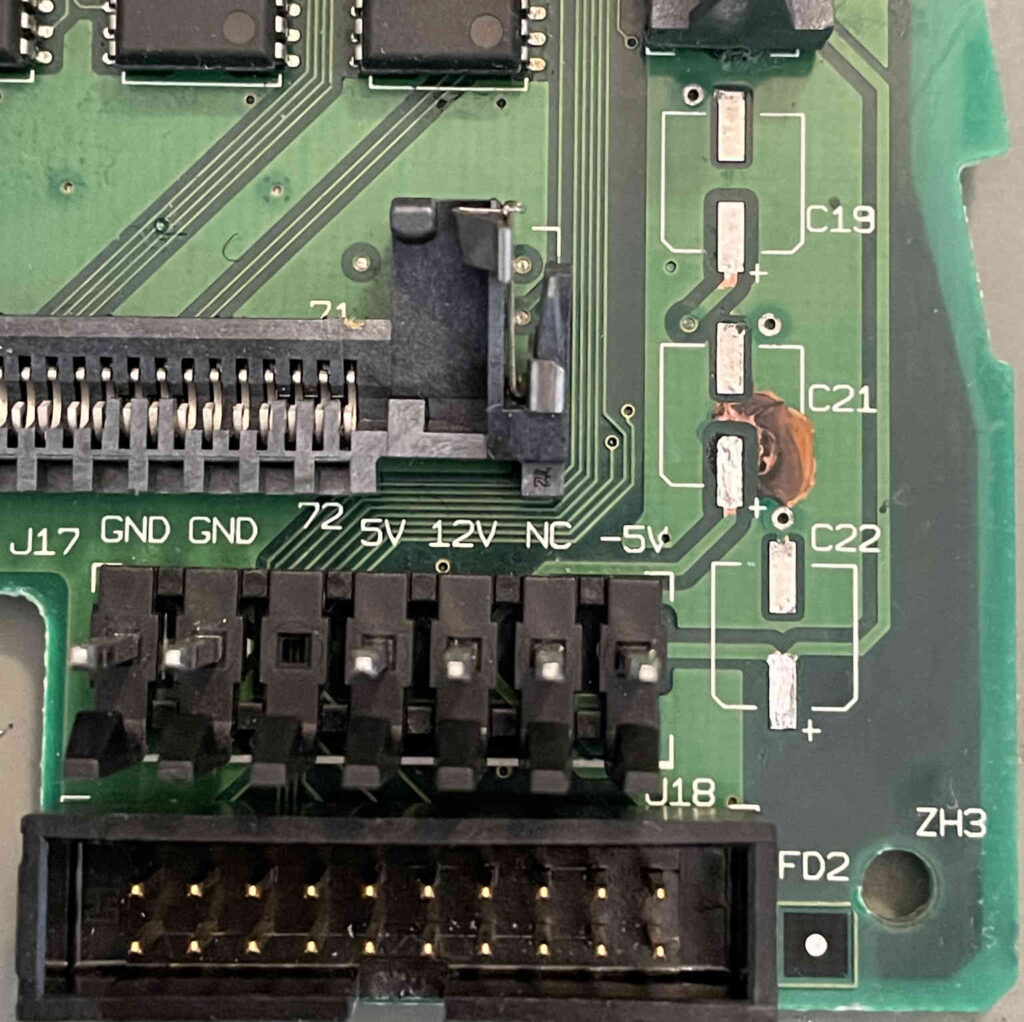
Yikes, C21 leaked really badly and damaged the solder mask and the copper underneath. When I removed it, there was a big puddle of goo sitting there. I haven’t installed new capacitors on this board yet, but I’m probably going to need to scrape more of that dark crud from the copper and cover it all up with UV-curable solder mask. Luckily, it’s just the ground plane so it’s not a huge deal.
Anyway, the important thing to note in this picture is that the negative terminal of each capacitor goes to the ground plane. The positive terminals all head over to pins on the power supply connector.
What’s happening here is there is one bulk capacitor for each of the three power rails provided by the power supply. C19 is for +5V, C21 is for +12V, and C22 is for -5V. You can see the trace from C22’s positive terminal going directly to the -5V pin on the power supply connector.
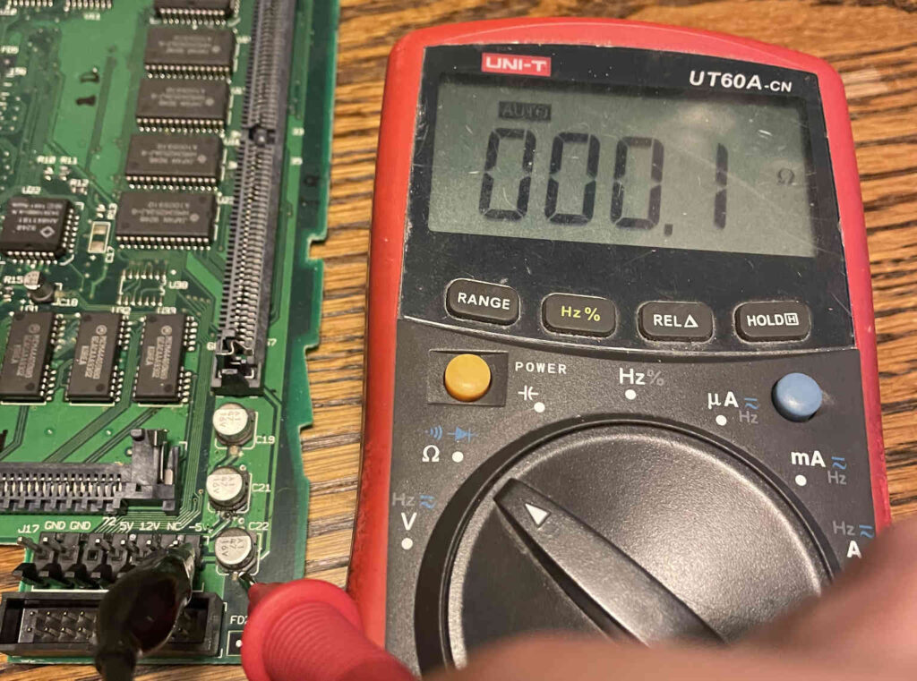
This arrangement makes sense for the two positive power rails, but it’s backwards for the -5V rail. If the image above isn’t proof enough for you, here are a couple of pictures with my multimeter definitively showing that the positive terminal of C22 goes to -5V and the negative terminal goes to ground. That means when the system is powered on, there will be -5V across this capacitor.
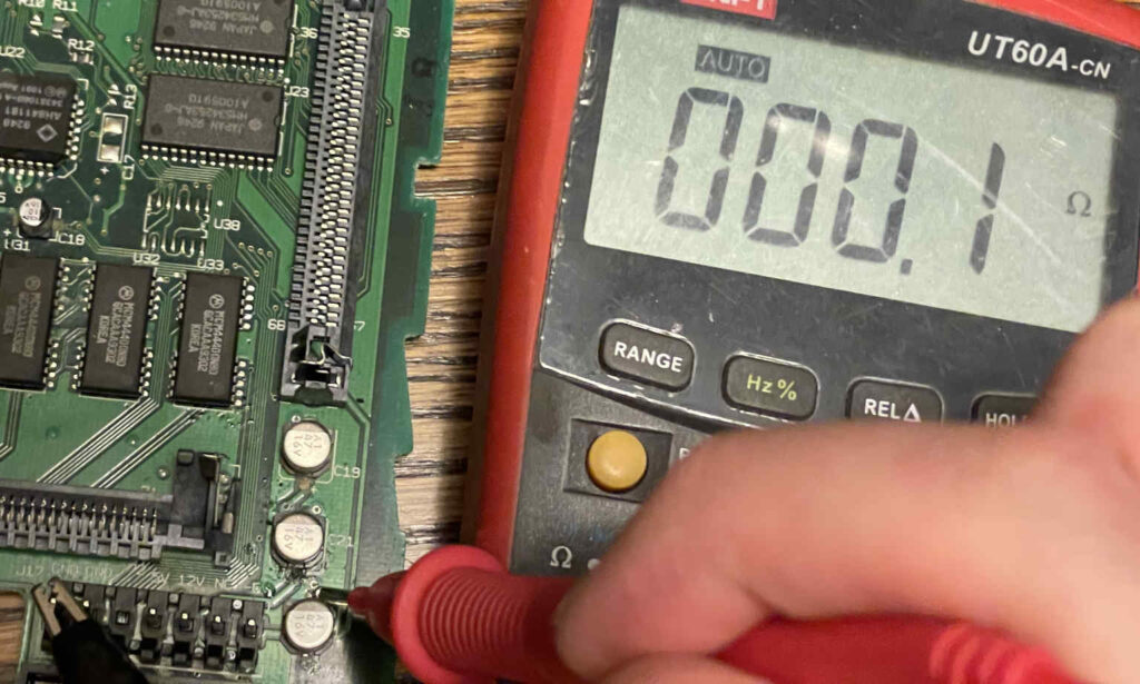
I really don’t need to do any additional analysis at this point in order to say that this is just plain wrong. You aren’t supposed to have a negative voltage across this type of capacitor. There’s a reason they have a marking that identifies the negative side. The voltage at the positive end should be greater than or equal to the voltage at the negative end. In other words, this capacitor’s positive end should have been connected to ground and the negative end should have been connected to -5V.
Let’s compare and contrast this circuit with the corresponding circuit on an original Mac LC, which uses the exact same power supply. This is another system with its original leaky caps:
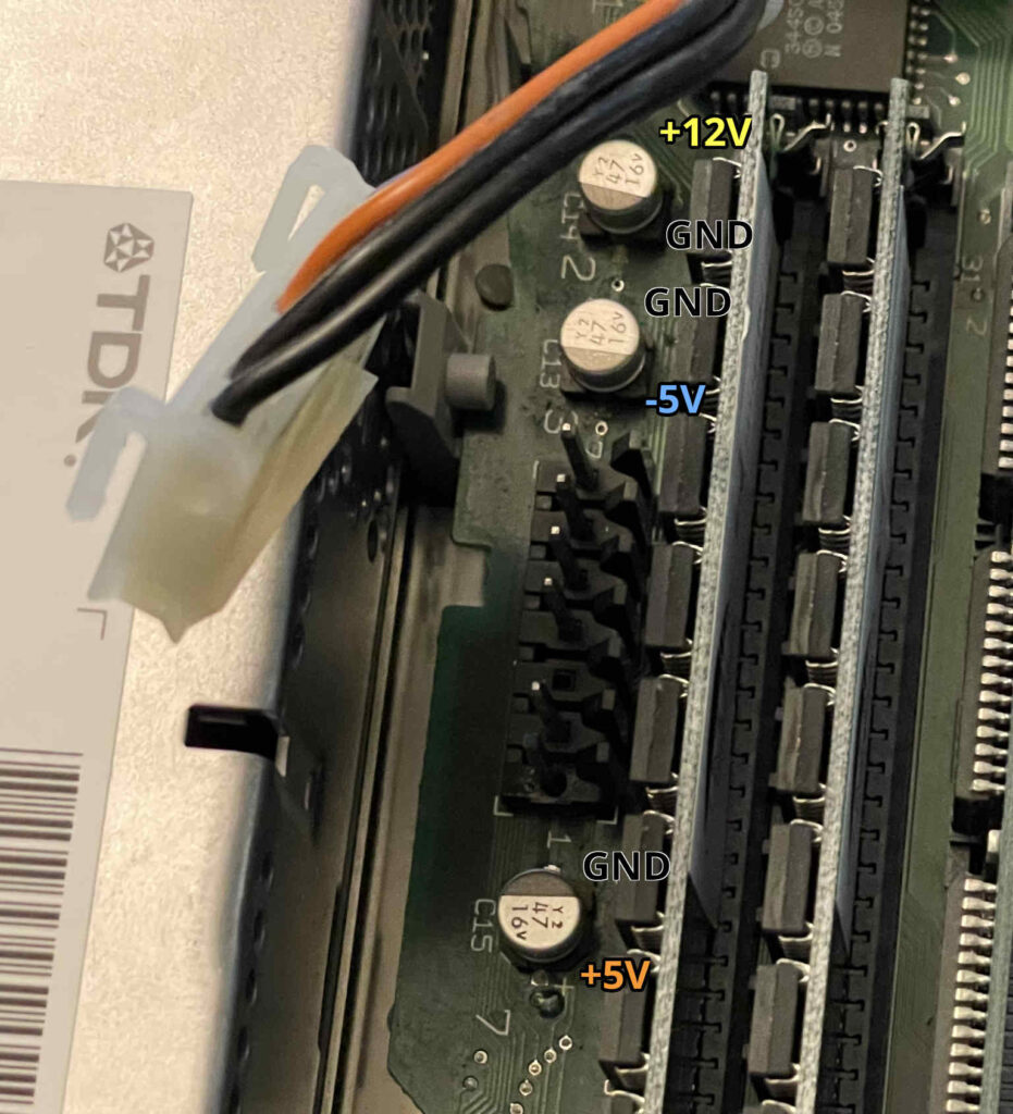
They installed it correctly on the original LC (and the LC II). -5V goes to the negative end of the capacitor, and ground goes to the positive end, resulting in a net voltage of positive 5 volts across it.
What about the LC 475, which is the successor to the LC III? If Apple miraculously discovered a special exception to the laws of physics during development of the LC III, I would expect them to have continued following this new rule with the design of the LC 475.
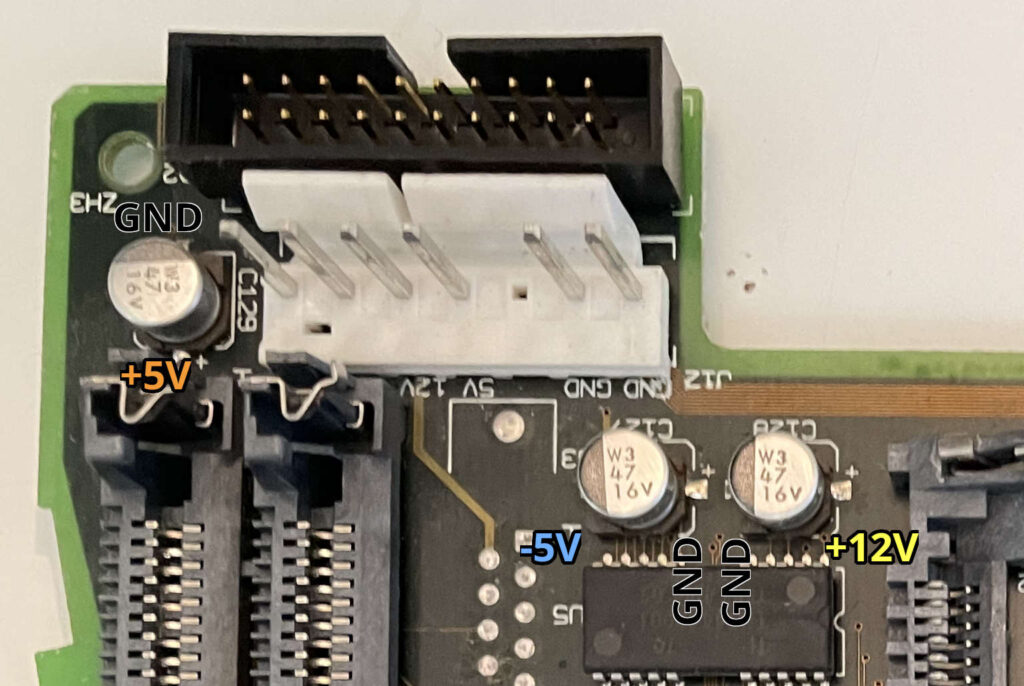
Nope! It’s back to the same (correct) orientation that was used on the original LC.
After seeing it myself and comparing the circuit with other Mac models of the era, I’m very confident that Apple made a boo-boo on the LC III. It’s not just a factory component placement issue; the PCB’s silkscreen is also incorrect. It’s basically the hardware equivalent of a copy/paste error when you’re writing code. I’m hoping to raise awareness of this mistake because all of the (very useful) recapping guide collections I’ve found on the Internet strangely fail to mention this reversed capacitor for some reason, even though it’s known to have caused problems for many people.
But, you may ask, why didn’t it matter with the original liquid-filled electrolytic capacitor fitted on the board? Why didn’t this cause a huge uproar back in the day? Why didn’t everyone’s LC III explode in a giant fireball? Well, for one, the original capacitor was obviously tolerant of this mistake. It was rated for 16V but only -5V was being put across it. According to what I’ve read online, that’s more than enough reverse voltage to permanently damage this type of capacitor, but it may not be enough to cause it to violently explode. Plus, it is only involved with the -5V rail, which is really only needed for the RS-422 serial ports. The capacitor might not have been doing its job properly if it was installed backwards, but it didn’t seem to really be hurting anything.
With the way that a lot of people in the hobby these days (including me) are using tantalum capacitors as replacements, I think it’s potentially dangerous that this backwards capacitor isn’t widely documented. Although the computer seems to work okay in this configuration with a normal electrolytic capacitor like what was installed by the factory, tantalum capacitors are not quite as forgiving when installed in reverse. Multiple people online have observed that when they have a tantalum capacitor installed in the original incorrect orientation, they end up with an incorrect voltage on the -5V rail. The original poster about this issue, paul.gaastra, said that with the tantalum capacitor installed backwards it was drawing 1.3 amps (way too much) and the voltage was only -2.3V. At best, this is going to result in serial port problems. At worst, you’re asking for the capacitor to explode or catch on fire. It’s probably not good for the power supply, either; it’s only rated for 75 mA on the -5V rail.
The bottom line is that Apple’s silkscreen markings and factory placement for C22 on the LC III are flat out wrong. There’s no other correct answer. Please, if you are recapping one of these machines, install C22 backwards from what the silkscreen on the PCB says. If you don’t believe me, or want to double check for yourself, you can easily verify this with a multimeter in continuity test mode with the system powered off. The positive end of the cap needs to be connected to ground, and the negative end needs to be connected to -5V. Using your multimeter’s DC voltage mode, if you power on the system, you should see 5V across the capacitor (negative probe to negative side of cap, positive probe to positive side of cap). That’s how it is on every other Mac with a -5V rail.


Interesting that C21 (+12V) failed, not the reversed C22(-5V).
Did you know that when electrolytic caps are manufactured, the two aluminum foil plates are identical and there is no insulating layer. Once assembled, with an electrolyte soaked porous sheet between the plates, a voltage is applied. This causes a chemical reaction with one of the plates, that creates a thin insulating layer. The layer surface also isn’t flat, but has a very complex structure with a high surface area, to maximize the capacitance.
This process is called ‘forming’ the capacitor.
The reason electros are (mostly) polarized, is that the chemical reaction can be reversed with opposite voltage, and as the ‘formed’ layer is removed, the capacitance (and voltage it can resist) decrease.
The insulating layer also degrades over time while there is no voltage across the cap. So to restore vintage electronics, power should be applied very slowly ramping up to full voltage, to allow old electros to ‘reform.’ (If they didn’t leak and dry out.)
But 5V is quite low. It’s possible that C22 completely de-formed, and then re-formed in reverse polarity. It didn’t leak and might even have been perfectly fine. Though replacing it was a good idea.
C21 otoh… An important spec sheet number for eletros is the maximum ripple current they can handle. The reason it matters is that electros have an internal series resistance, and the ripple (AC) current is dissipating heat in that resistance. Cheap little caps like these will have relatively high internal resistance. And the +12V rail can have a fairly high ripple current.
It would not surprise me at all if no one at Apple checked the +12V rail ripple current in this cap, or ever even looked at the spec sheet for the caps. That C21 leaked, suggests it was under-rated, and over time internal heating and resulting eletrolyte pressure broke the seal.
Hi Guy,
Thanks for the details about how caps work and how they are made! To be fair, all of the electrolytic caps had leaked on this board, including the other two in the picture. I think it’s more an old age thing than anything else. It’s a super common failure mode on lots of old electronics. Every Mac from the early ‘90s I have encountered has had caps with leakage like this. C21 was definitely the worst I’ve ever seen though.
I tried to fact check the statement regarding
> the two aluminum foil plates are identical and there is no insulating layer.
It doesn’t seem accurate, at least not with today current manufacturing techniques.
One of the plate is highly etched beforehand to allow for the formation of the oxide layer. Also, the purity of the plates differ.
The two multimeter photos are same?
Great writeup Doug! Apple surely must have known at an early stage, so it really makes you wonder if they made any tests verifying that it would sort of work anyway and therefore decided against doing a recall on it.
Thank you for posting about this! I’ve been trying to find known examples of these kinds of issues but haven’t run into any myself yet. I run Caps Wiki and someone had made a page about the LC III but had not mentioned it. I just updated the page to document this issue there as well. I’ve heard that ASUS also had a tendency to get the silkscreen wrong on their caps but they would install them electrically correct. So this issue can show up in other ways as well.
Robo, the pictures are subtly different. In the first one I’m clipped onto the -5V pin of the power supply and probing the positive terminal of the cap. In the second one I’m clipped onto ground and probing the negative terminal. In both pictures the multimeter shows continuity.
I agree Joakim, I feel like Apple must have been aware at some point. With the stock caps it didn’t seem to be a problem. The old cap didn’t look worse than any of the others after all these years.
Thank you Tech Tangents! That’s great. Your updates on the page look awesome. Much appreciated!
I believe that -5V was already almost obsolete by the time of the original IBM PC.
[…] ↫ Doug Brown […]
[…] with its original leak capacitors," he can double-check Apple's board layout 30 years later and detail it all in a blog post (seen originally at the Adafruit blog). He confirms what a bunch of multimeter-wielding types long […]
I noticed that already 2 or 3 years ago when I recapped mine…
Told that to Bruce but he didn’t want to fix his recap guide 😛
Yeah, and the 68kmla thread I linked in this post is over 10 years old. The info has been out there for a while. Here’s hoping that some of the other capacitor references update their info like Tech Tangents kindly did. I’m trying to raise awareness about this issue because installing a tantalum cap backwards is a safety hazard in my opinion.
Also, since there has been a bit of confusion in the comments on the Ars Technica article, I just wanted to clarify to everyone: my blog title is kind of misleading. It’s not really the factory’s fault; the silkscreen on the board is wrong too. It’s a design mistake by Apple. The factory followed what the board design said to do, which was wrong.
I’m just wondering if they goofed on the schematics or if they had it right and someone screwed up when routing trying to “fix” it.
Ahh yeah, that’s a great question mmu_man. I’m not sure what tools Apple used for schematic capture and PCB layout back then, but based on the workflows of modern tools it seems to me like a schematic mistake is more likely. Who knows though!
For anyone following along who is curious about the actual repair of the logic board, here’s my progress on that. I scraped the gunk from the copper so it was nice and shiny.
Then I used a little bit of UV-curable solder mask:
And applied it with a toothpick and cured it with a UV flashlight. I’m still getting the hang of using this stuff, so it might be a bit on the messy side.
Then I soldered in the replacement capacitors, being sure to reverse C22 as explained in this post. I know C19 looks a little crooked, but it was right up against the plastic VRAM socket and I didn’t want to risk any damage. I care more about the functionality than the looks here!
After replacing all 11 capacitors, it booted straight up into what I have to assume is the original factory install of System 7.1P2. Yay!
Nice one Doug! Just continuity checked my LC III and can confirm your finding. In my case, I do actually have a recapped tantalum in C22 in the original orientation, and you’d never know it, the Mac runs perfectly and the cap hasn’t blown up. But I’ll get it on my to do list to swap it over.
Thanks Jakeys! Interesting, I’m glad it didn’t blow up on you! Is your -5V rail actually at -5V? I know others with tantalum caps installed in the factory orientation reported it was only around -2.5V and drawing a bunch of current.
Yeah, -2.3V here too. I guess the cap’s probably toast, but the Mac and the PSU seem okay. Has been powered on in this configuration since being recapped for tens of hours at this point, if not hundreds. I’ll still get it replaced anyway.
Looking at it further, the person on 68kmla who said their tantalum C22 caught on fire wasn’t using the stock power supply that was originally installed in the machine; they were using an aftermarket one.
Perhaps the reason that people usually see an incorrect voltage rather than the cap exploding or catching fire is because the stock power supply isn’t capable of supplying much power on the -5V rail.
That’s great…except the power supply in all the LC models is something that tends to regularly go bad due to capacitor leakage, so it’s not out of the question for people to use aftermarket power supplies as their repair, which may have more capability to supply current on the -5V rail. Maybe it’s a point in favor of repairing the original supply rather than using something aftermarket that hasn’t necessarily been qualified. I’m 3 for 3 on LC TDK power supply repairs so far, so that’s good! Although one of them had super duper leaky capacitors and required some heavy cleaning work.
Recap-A-Mac has also been updated with the C22 reversal info now! Yay! I absolutely love that site so I’m glad it has the correct info.
Great article and follow-ups. Really nice to see someone give those old machines some TLC they well deserve!
One remark though – that is way too much UV-curable solder-mask.
This stuff does not transmit UV very well at all. So, if one applies any thicker than few hundred microns, what can happen is – thin hard/cured crust forms, superficially looking solid. But underneath, it’s still gooey. So, no adhesion to the board; hard crust just floats. If there’s any future stress, mechanical or thermal cycling, that crust can crack.
Thanks kees99!
Yeah, I probably picked a bad project for my first try at using that solder mask. It was difficult to apply it really thinly with the toothpick. I almost wonder if something like a miniature squeegee would be better. I did cure it for a really long time and pressed down on it pretty hard afterward to test and it seemed fine, but you may be right. I’ve seen others mention the same thing about how you end up with an uncured core underneath. If anyone out there is reading this, definitely apply it thinner than I did!