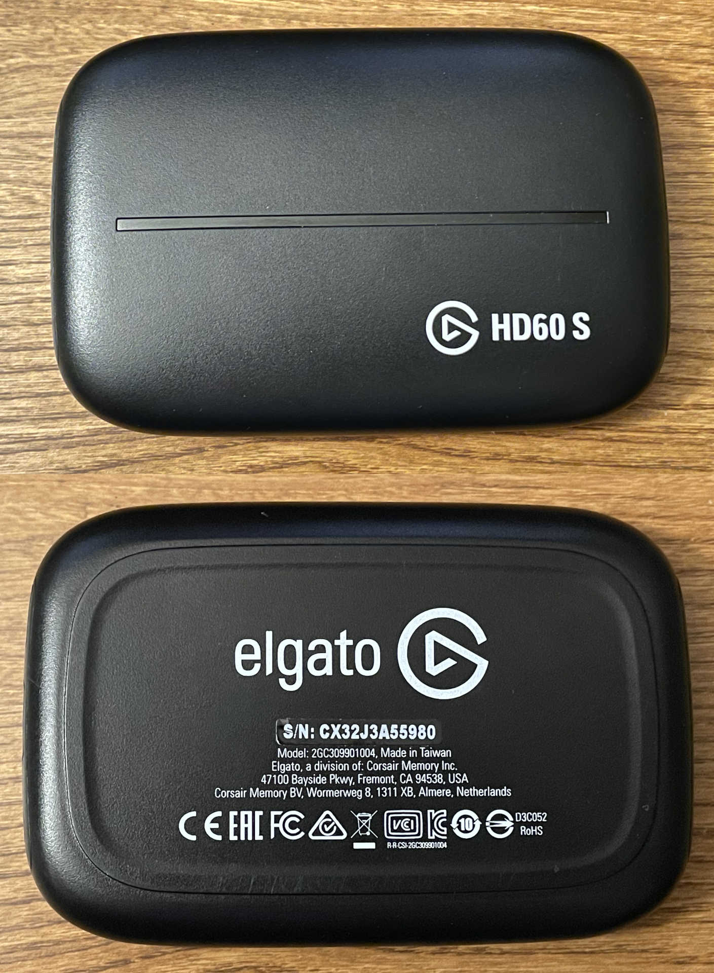
Here’s a weird problem that I’ve never seen before, along with my eventual hardware fix. After my previous Elgato Game Capture HD60 S HDMI capture card LED repair escapades, I recently ended up trying to find another modern revision of the same device so I could dump its SPI flash chip in order to be 100% certain that the data I put into the flash for the animations was correct for the newer model. I took a chance and bought one for cheap on eBay that was sold as not working at all, but looked like it was newer based on the case style and arrangement of the back panel:
The item description said:
Unit powers on when connected to computer, but all computers we’ve tested this with refuse to recognize it as being connected.
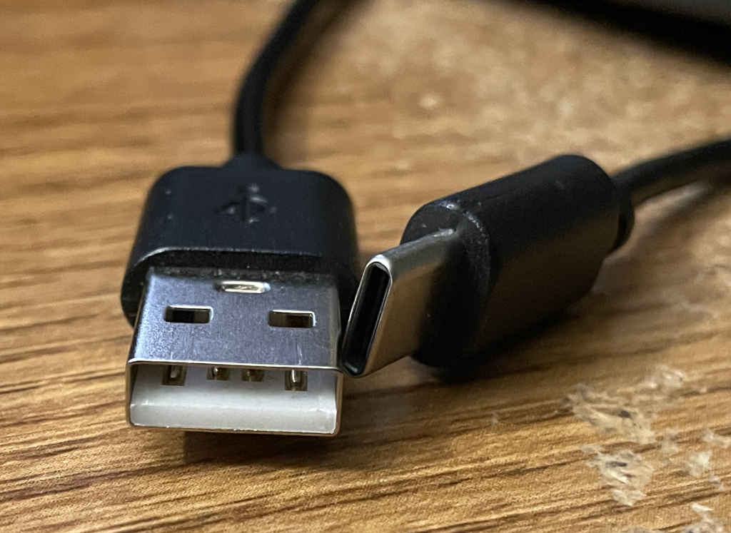
When it arrived, I noticed that it came with a USB A-to-C cable that wasn’t actually a SuperSpeed cable.
Would it really be this easy? Spoiler alert: No.
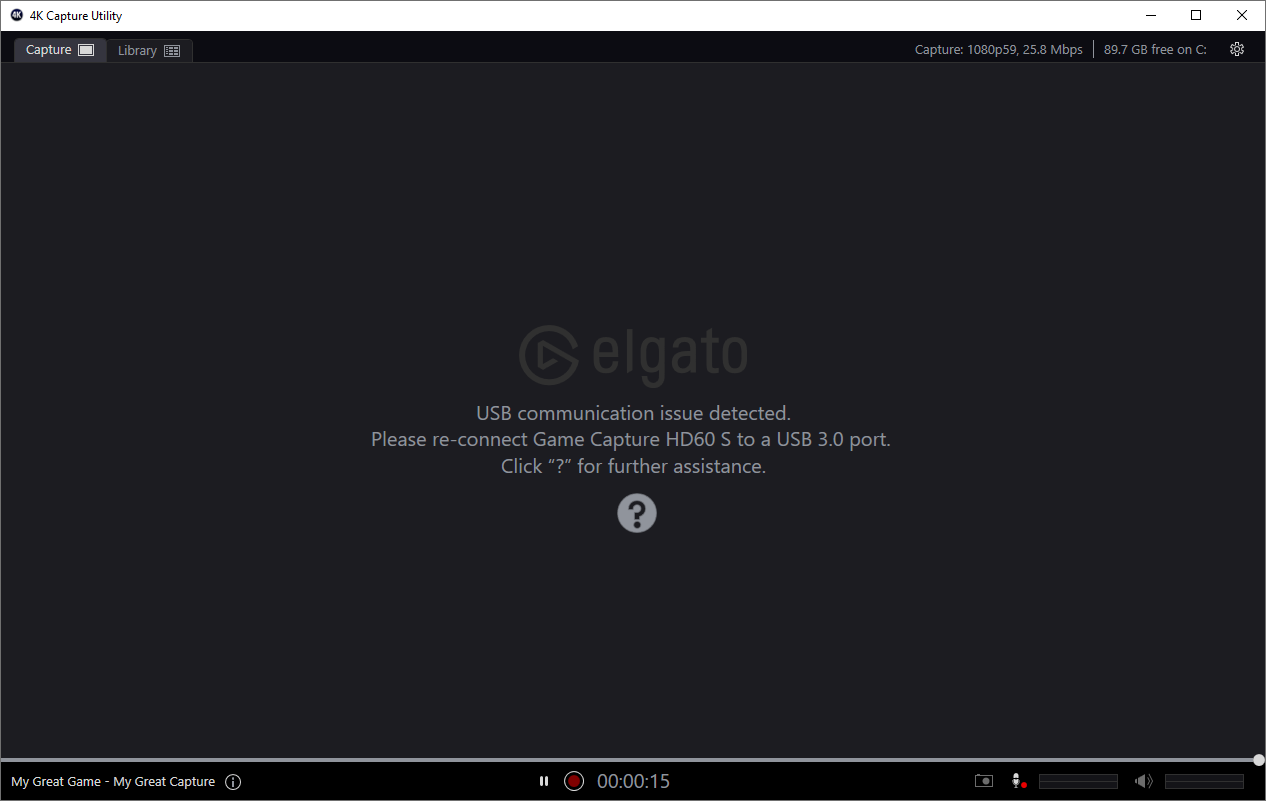
Even using a known-working USB 3.0 A-to-C cable, I replicated exactly what the seller claimed. When I plugged it into my computer, the status LEDs blinked white as they were supposed to, but Windows 10 almost immediately played the USB disconnect sound. If I left it plugged in long enough, I would sometimes see a message on the screen about a connected USB device malfunctioning. I didn’t care that it was broken though. To be honest, I was more excited about it having working LEDs.
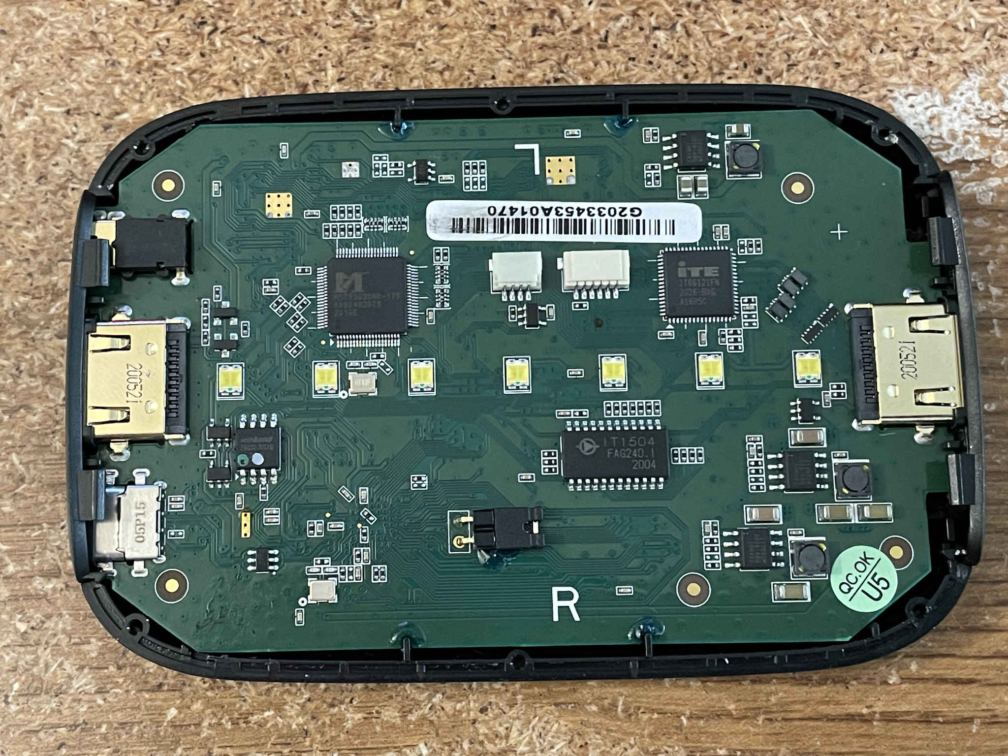
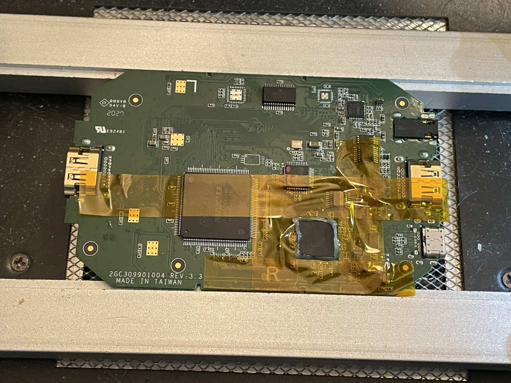
That excitement quickly faded when I opened it up and discovered that it was an older model of the HD60 S in a newer enclosure — it used an MStar MST3363CMK chip for HDMI capture instead of the ITE IT6802E, and the microcontroller was a Nuvoton NUC100 instead of M031. It was still based on the CYUSB3014 at least. I already had a couple of working examples of these older versions of the HD60 S, so I couldn’t really learn anything new about the LEDs from it. Instead, I was left with a new interesting challenge: could I fix it?
One of the first things you should do when you run into funkiness with USB-C ports is to try reversing the direction you’re plugging in the cable. Sometimes port failures or chip failures cause a cable to only work in one orientation. This device was broken both ways, so that wasn’t it. I also noticed that if I quickly unplugged and replugged it enough times, sometimes it would stay connected, but Elgato’s software would warn me that it couldn’t be used because it was connected to a USB 2.0 port (it wasn’t).
Next, I tried other computers. It also failed the exact same way on my laptop running Windows 11. If I plugged it into a computer running Linux (even the same laptop booted into Linux), it would stay connected as a USB 3.0 device just fine. Too bad there aren’t any Linux drivers for it. Maybe that would be a fun future project.
Anyway, this led me to try plugging it into my M2 Mac mini. Even though Elgato said the device isn’t compatible with ARM Macs, I went ahead and tried it for fun.
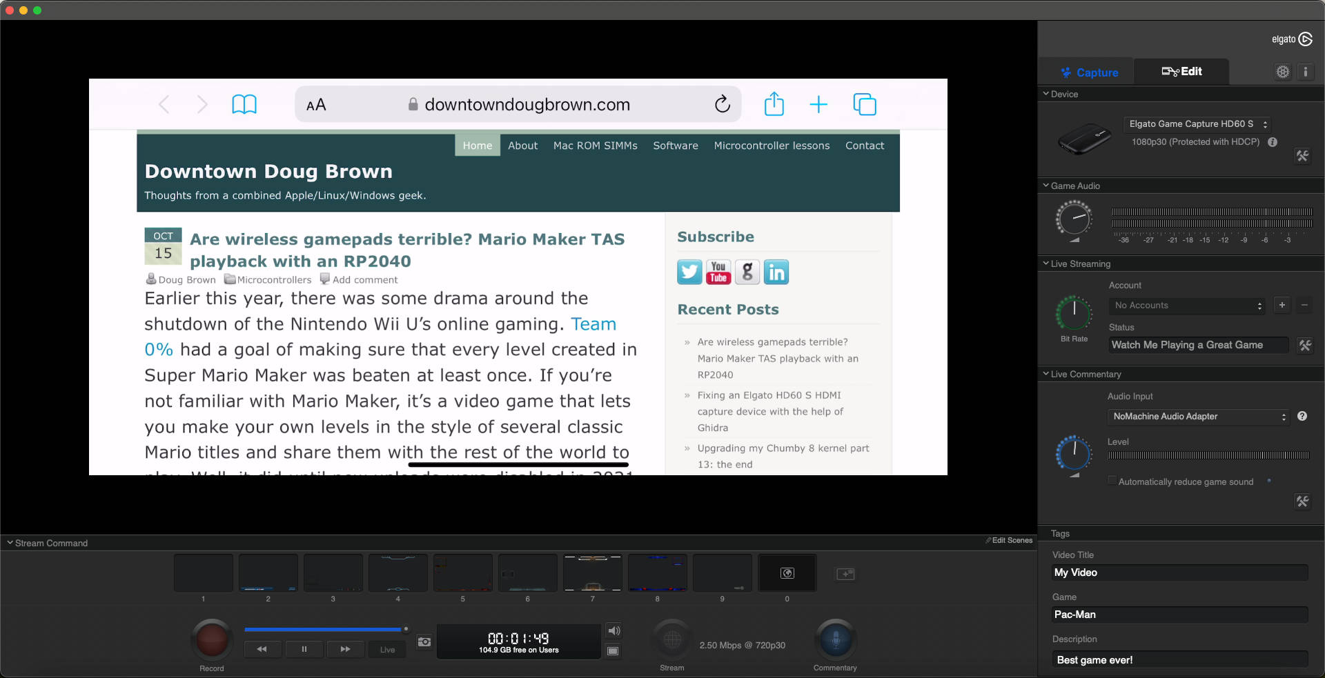
Much to my surprise, it worked perfectly fine when connected to my Mac. It was able to capture and display the incoming HDMI signal with no issues whatsoever. What the heck? This felt like proof that it wasn’t actually a hardware fault.
But the thing is, it kind of had to be a hardware problem. I had collected two other similar older revisions of the HD60 S, and they both worked fine on all of my Windows machines, both Intel- and AMD-based. This partially-faulty device didn’t work on any of them. I even booted my newest machine, which is dedicated to Linux, into Windows 10 using a Windows To Go USB stick created with Rufus. I replicated the exact same problem on it too!
Here’s where I really narrowed things down. I booted back into Linux on that machine, started up my Windows 10 VMware VM inside of Linux, and then plugged in this troublesome HD60 S.
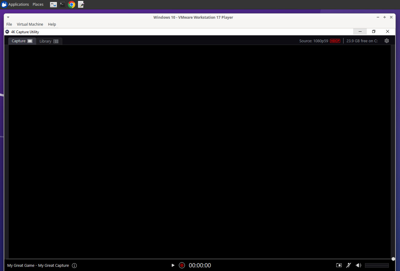
Although the video display in Elgato’s software didn’t work, the device stayed connected just fine and it updated its displayed signal status as I plugged in various HDMI sources. I’m pretty sure the video display not working was just an incompatibility with VMware’s display driver or something.
The common denominator was: when the actual computer was booted into Windows, it didn’t work and would disconnect immediately. When it was booted into Linux or macOS, it worked fine.
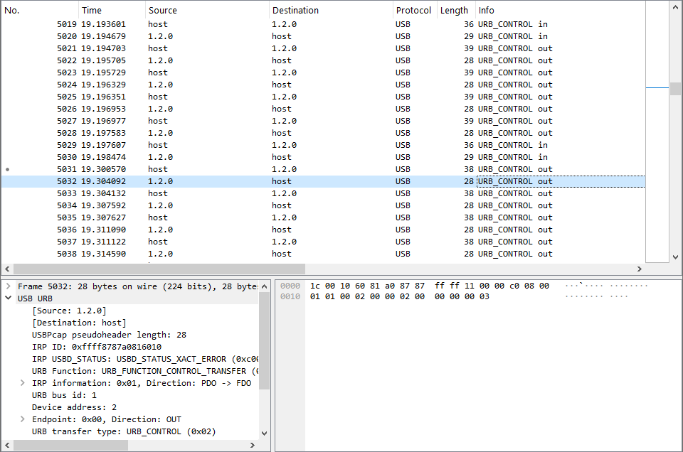
I don’t have a hardware USB 3.0 analyzer because they’re way too expensive. Instead, I used Wireshark and USBPcap to dig into what was happening in Windows when the broken device would disconnect. The driver was doing a bunch of vendor-specific control transfers, presumably to configure the newly-discovered device. At a random point which varied in every capture I saved, the returned status would be USBD_STATUS_XACT_ERROR for a few USB transfers, and then everything would break down from there. Some Googling found a Usenet post from a Microsoft engineer in 2003 explaining that, at least for EHCI controllers, that status code meant the host controller detected some sort of error.
I decided to use my USB captures to create a simple libusb program to replicate the problematic control traffic so that I could try to induce the problem when the device was plugged into a Linux or Mac host computer instead of Windows. What I found was interesting. When plugged into Linux or Mac, even if I replayed the exact traffic that caused it to disconnect in Windows, it was fine.
The real smoking gun was when I started up a Linux VMware VM on my Windows host machine and plugged in the HD60 S. It was fine at first because Linux doesn’t have a driver for it and thus doesn’t send any traffic, but then I ran my libusb program to start playing back the vendor-specific commands. This caused the device to disconnect! I was convinced at this point that there was a strange hardware problem that caused the device to be incompatible with USB 3.0 host controllers that were set up by Windows. This was all the software research I really needed to do.
Just to rule out software even more, I dumped the SPI flash contents from this problematic device. As a reminder from last time, this chip contains the firmware for the CYUSB3014 as well as the LED animations. Other than the USB product ID, manufacturer string (Elgato vs. Elgato Systems), serial number, and checksum, the firmware was 100% identical to what I dumped from my first newer HD60 S that I originally repaired in my previous blog post. Also, the stored LED data was a perfect match to what I had copied from one of my other working older-revision devices. I felt pretty confident that there was nothing wrong with the software running on the CYUSB3014 to cause this. I also confirmed that the firmware running on the Nuvoton microcontroller was fine and fully updated, but that wasn’t a surprise. If anything was really wrong in firmware/software, it shouldn’t have worked properly on my Mac.
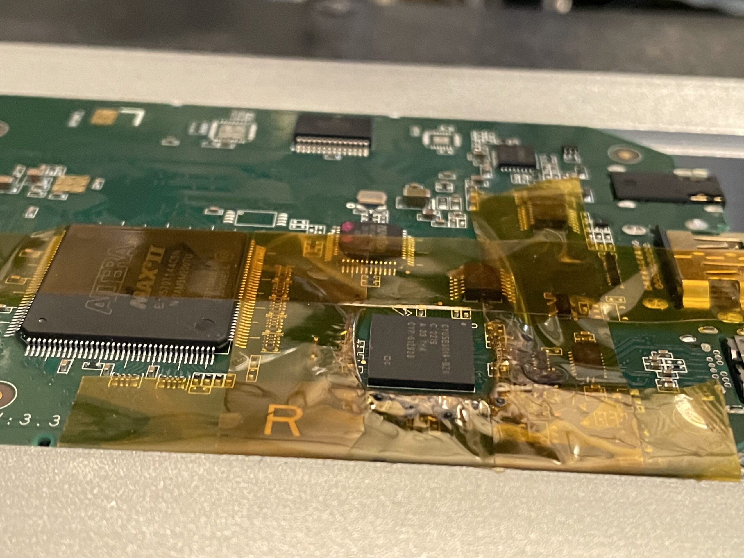
Off to the hardware I went for some very basic reverse engineering. Luckily, the USB circuitry on this product isn’t very complicated. In fact, I can fit all the really important stuff into one single microscope picture:
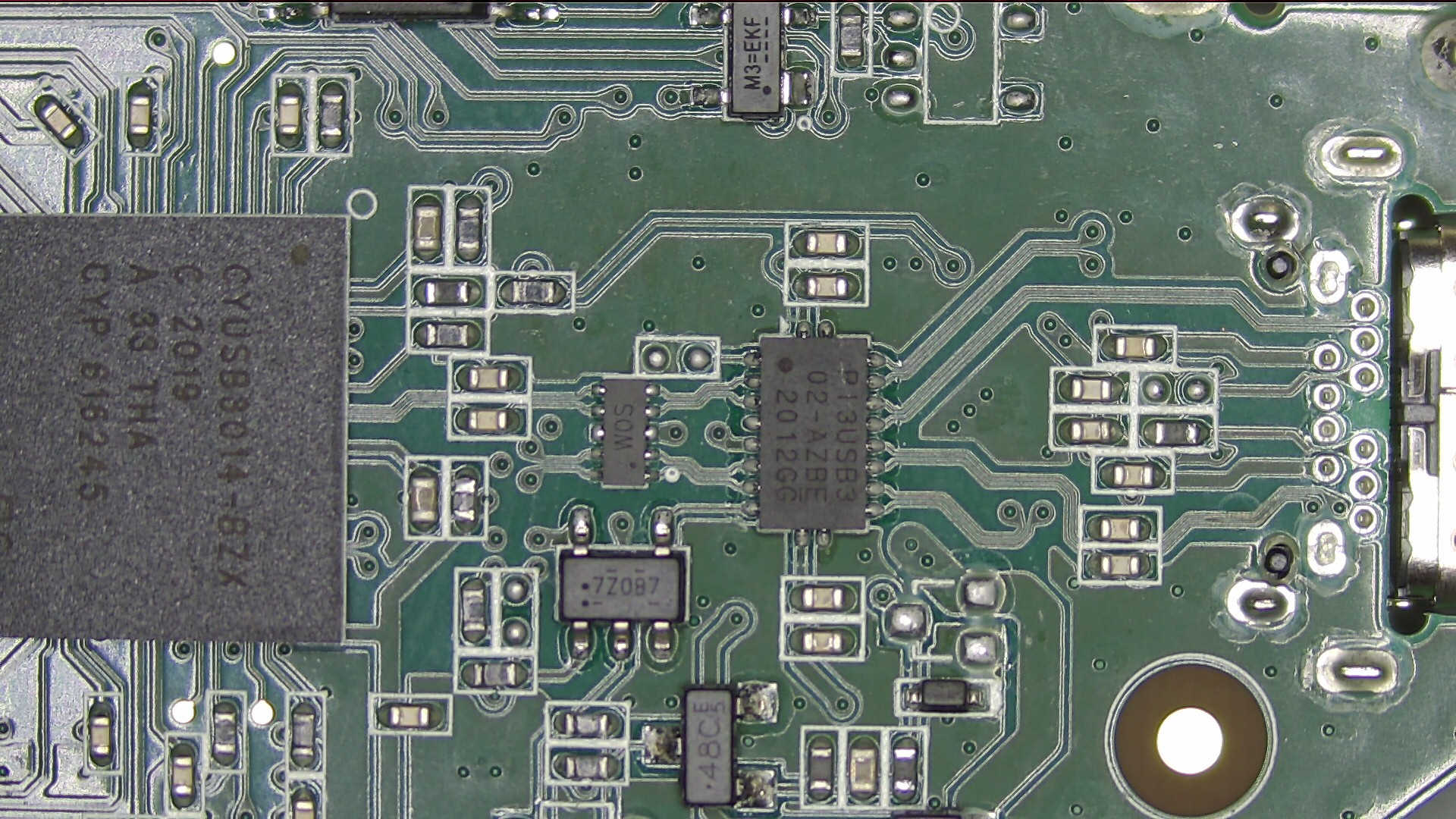
The USB-C port is on the right. For USB 3.0 communication there are four differential pairs going from the USB port into the eight pins on the right side of the Diodes Incorporated PI3USB302 chip: Tx1+/-, Rx1+/-, Tx2+/-, and Rx2+/-. Only one set of Tx and Rx pairs will be used at a time. The reason there are two Tx and two Rx pairs is because the USB-C cable can be reversed. The PI3USB302’s job is to pass through the USB traffic on the correct set of pins based on the cable orientation. With fast 5 Gbps traffic, you can’t just tie the lines together on opposite sides of the port; they have to go through a mux chip like this.
There’s also a single differential pair on the opposite side of the board for USB 2.0 480 Mbps traffic (which is tied together on both sides of the USB-C port and doesn’t need a mux), but I didn’t really feel that it was relevant to the problem I was seeing. Clearly the device was in SuperSpeed mode when failures occurred, so I ignored the USB 2.0 lines.
From the PI3USB302, a single set of Tx and Rx pairs goes to the CYUSB3014 chip. It passes through a small chip marked WOS which appears to be an array of four TVS diodes for ESD protection. That’s all there is to the circuit, aside from some series capacitors. This was actually pretty nice. There weren’t many things that could possibly be blamed, and I could narrow it down quickly.
- I confirmed that the PI3USB302’s mux SEL pin was correctly being changed based on how I plugged in the USB-C cable.
- I swapped the PI3USB302 on this problematic board with the same part from a known-good HD60 S. So the good board had the bad board’s chip and vice-versa. This exonerated the PI3USB302, because the known-good device kept working and this broken device was still broken.
- I tried temporarily removing the TVS diodes. This didn’t change the behavior, so the TVS diodes were okay and I put them back on.
- I temporarily removed the series capacitors and replaced them with wires. Nothing changed, so the capacitors were probably okay. I reinstalled them too.
This left only two possibilities: some weird problem with the USB-C port itself, or the CYUSB3014 main processor was damaged. Nothing else was involved in the USB communication. I really doubted the USB port could cause a problem like this, so I focused on the CYUSB3014. Unfortunately, it’s a scary BGA chip with 121 solder balls underneath in a 1 cm x 1 cm package. Yeah, it looks huge in the microscope picture above, but it’s one square centimeter in area. I’m sure you can imagine how tricky the soldering was to perform all the tests listed above if you keep that scale in mind.
Despite being very intimidated by BGA soldering, I decided to try replacing the CYUSB3014. I had never successfully replaced a BGA chip, although to be fair, I had only tried (and failed) one previous time in the past. I shopped around for the CYUSB3014-BZXC. I was pretty surprised to discover that Digi-Key and Mouser both wanted over $30 for a single chip. That’s more than double what I paid for the entire broken device, even taking shipping into account. Thankfully I remembered that while building Alex Taradov’s USB 2.0 sniffer, I had noticed that he suggested LCSC as a less expensive but legitimate supplier for a different Cypress/Infineon part. I was so glad he mentioned this, because the same knowledge applied to this part too. LCSC had the exact same chip available for well under half the price. This allowed me to buy two of them so I’d have an extra in case I really screwed up my first attempt. I had to wait a while for my package to arrive from China, but it was worth it.
Less than two weeks later, the package arrived and I got everything ready to try swapping out the chip. I put it on my preheater and let the whole board warm up, added some flux, and then used my hot air station to remove the chip. As usual, I used Kapton tape to help prevent me from screwing up nearby components. I’ve also learned that in situations like this you don’t want super high air flow because that’s another way to send small resistors and capacitors flying everywhere. I set my station for about 50% flow or so.
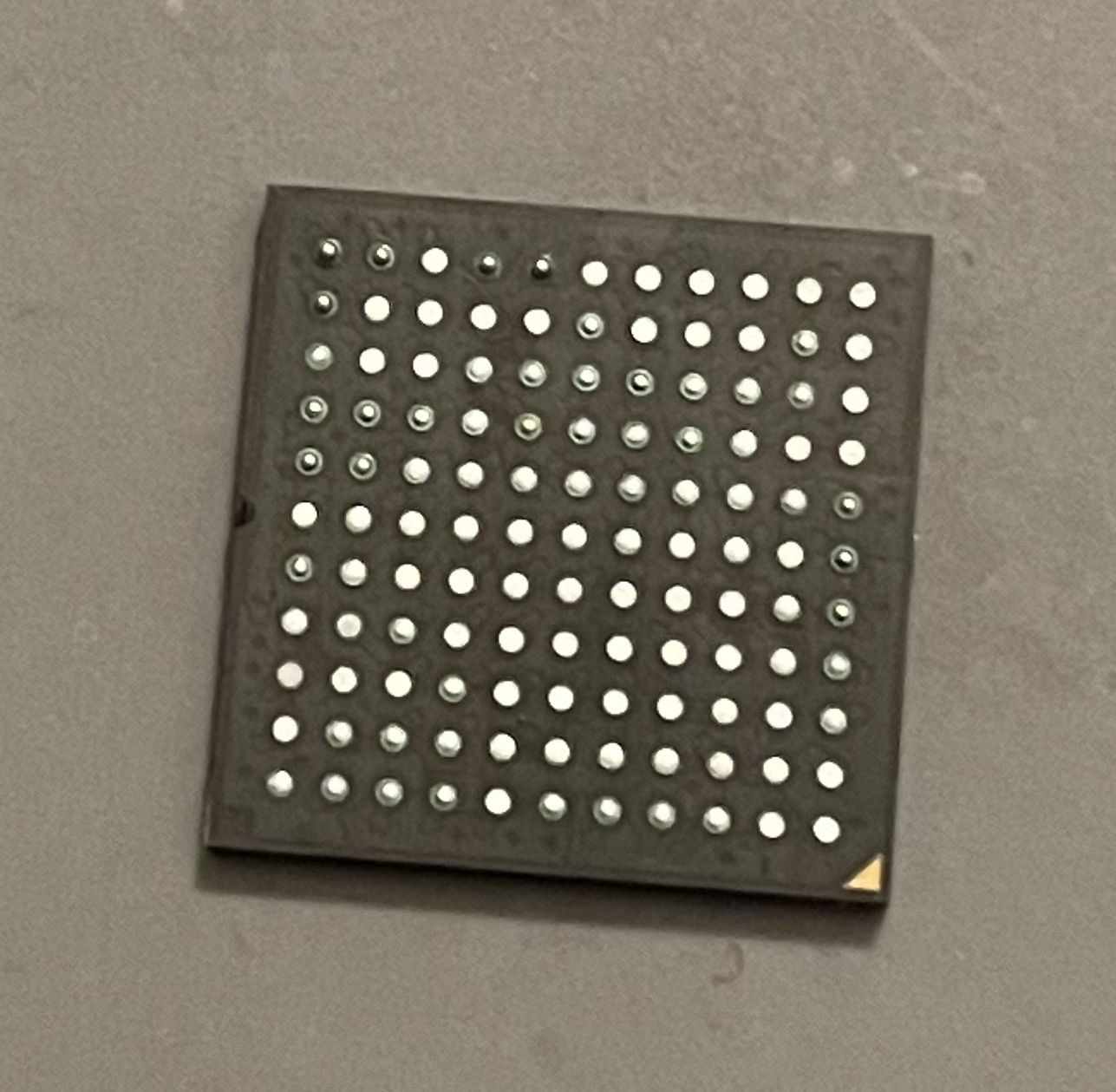
Here’s the bottom of the old chip after I removed it and cleaned off the flux. Keep in mind those little solder balls are spaced on a 0.8 mm pitch, meaning that’s how far apart they are from each other, center-to-center. It’s tiny.
I dabbed some fresh leaded solder onto the PCB’s pads and then used solder wick to clean them up (sorry, I didn’t take any pictures!) and applied a thin layer of new flux. Then I placed one of the new chips on the board and carefully nudged it into place. Helpfully, the PCB had a silkscreen outline showing exactly where the chip should be. When I was satisfied, I turned on my hot air. I kept the air going for a while until I thought the chip was soldered down. I could tell it was at least partly soldered because it would jump back in place when I lightly tapped it from the side. So then I let it cool off.
I was left with what looked like a pretty decent soldering job. It was definitely much closer to the PCB than the original chip, though, so I’m pretty sure the original soldering job at the factory had also used solder paste on the actual PCB pads.
I anxiously plugged it in, and was very excited when it was recognized as an Elgato Game Capture HD60 S! The Elgato software recognized it just fine. It didn’t disconnect! At this point I was feeling pretty good about my soldering job, and very confident I had made the right call to replace the CYUSB3014 — if anything else was the cause, I would have expected the disconnection problem to still be happening.
So then I was ready to really test it. I hooked up an HDMI source. The Elgato software pointed out that I had plugged in a 1080p source, but nothing showed up on the screen! Nada. Just a blank image. I tried plugging it into my Mac and it had the same problem. One time I got a green screen, and another time I got a red screen. I tried holding my finger down on the chip really hard and at one point I saw a frame or two that looked almost correct, so I was pretty sure it was a BGA soldering mistake.
Most people are smart enough to remove the whole chip and redo everything when something like this happens, but not me. I knew that the pads were totally clean and the chip had been precisely placed, so I was pretty sure I just didn’t solder it down all the way. I added more flux and reheated everything again. At this point I was done with the Kapton tape, by the way. The low air flow was perfectly safe for not sending tiny components flying everywhere. I wondered if maybe I hadn’t done a great job of heating around the edges, so I tried to focus more on the edges.
After it cooled back down, I plugged it in. Somehow, my reheating job actually made it worse! It was still recognized just fine as a USB device, but I was always getting the warning about it being plugged into a USB 2.0 port. I must have screwed up the soldering of one or more of the balls associated with the USB 3.0 signals. Whoops!
All of these heating cycles began to concern me for the health of the board, but this led me to attempt number three at soldering the chip into place. Perhaps stupidly, I refused to remove it and start over from scratch because I still felt like I had done an excellent job of placing it, so I wasn’t worried about issues underneath like solder balls shorting together. I added more flux, and this time I heated it more than I thought was needed. It wasn’t enough to cause any popcorning or damage, so no worries there, but I was heating it probably about 10-15 seconds after I thought all the solder was already molten. I tapped the chip gently from the side and watched it jump back into place, and then I did one last thing before removing the heat: I gently pushed down on the chip from the top, in the hopes that all of the balls would stick to their pads.
Then I waited one last time for it to cool off, and finally plugged it into my Windows computer. At this point I was predicting that I would probably have to remove the chip if I couldn’t get it to work this time.

Somehow I got lucky with this final reheating attempt because it fixed everything! The captured video looked perfect, and it worked fine on both Windows and macOS. Yes, that’s right! Success! For the very first time, I finally soldered a BGA chip without screwing it up. It took me three tries, but I freaking did it!
I keep re-testing this newly-repaired Elgato HD60 S thinking it’s bound to fail after it has been sitting for a while, but it has passed every test I’ve thrown at it. I couldn’t stop smiling for an hour after I fixed it. BGA soldering is a lot harder than it looks, but it’s also not impossible to do. I really think my soft downward tap is what made the difference. It may be a terrible practice, but it worked. Also, I am 90% sure that when soldering a chip like this you’re supposed to use solder paste on the actual PCB too, but I didn’t have a stencil for it. Even if I did have a stencil, I have a feeling it would have made a huge smeared mess when I was trying to position the chip on the board.
Overall, this was a very successful fix. It was great to be able to confirm my diagnosis: there was definitely some kind of weird problem with the original CYUSB3014 chip on this board. Maybe it was slightly damaged from ESD that the TVS diodes weren’t able to prevent or something? I still find it super weird that it worked okay on Mac (or even Linux), but not Windows. It’s almost like Windows is configuring the xHCI host controller just ever so slightly differently enough that it’s not able to recover from whatever error was happening with the bad chip. I’ve never seen a problem like this in my life. It felt like voodoo. That’s why I’m leaning toward thinking the original failure was caused by ESD damage. I could be totally wrong here, but it makes sense to me. Does anybody have any other ideas about what could have happened here?
As a side note unrelated to this problem but very relevant to my previous LED repair post, I found something interesting while examining my Wireshark captures. Some of the USB control transfers sent to the CYUSB3014 contain data starting with 0xAB 0x03 0x12:
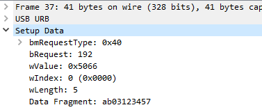
Amazingly enough, this starting pattern of bytes matches the “junk headers” I found in the corrupted LED animations stored in SPI flash on the previous unit I repaired:
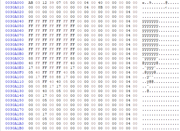
This makes me wonder if this is a clue about how the LED animations were corrupted on the HD60 S from my last post. Maybe USB control command data was accidentally inserted directly into the SPI flash. It would be interesting to see if the actual LED animation setup commands start with 0xAB, 0x03, 0x12, 0x39 just like what ended up in the flash chip depicted above.
In general, I think this repair probably marks the end of me trying to verify that my LED fix from my earlier post is totally correct. Since this device’s SPI flash dump is essentially identical to the SPI flash from the newer device on which I fixed the LEDs, and the LED data on this device still matched what I saw on older devices, I’m feeling more and more confident that this is the correct animation data for all revisions. This revision was sort of a “missing link” between the older and newer revisions. All in all, good news across the board!
Who knows though? If I see another broken one pop up on eBay for less than $10 in the future, I might take it on as another challenge. I still have another brand-new CYUSB3014 waiting to be used for something!


Hey! Thanks for the entertaining read! You have gained one reader. (+1 to readership)
Thanks Ben! I really appreciate it!
Hi Doug, I have this exact issue with my 2nd hand HD60S. The LEDS do work just as you described and the USB connect/disconnect issue on Windows is identical.
I do not have the tools or knowledge to replace a chip as you described, so unless Elgato RMA it (unlikely, I don’t have the original receipt and its probably way out of warranty) its junk to me.
If you are in Australia, I can post to you, probably not worth to send it international if you overseas.
Thanks for a brilliant write up, as always,
Steve, Canberra, Australia