This post has a little bit of everything. Hardware diagnostics, some suspiciously similar datasheets from two separate Taiwan chip manufacturers, and firmware reverse engineering. Read on if that sounds like fun!
Lately, I’ve been enjoying watching random electronics repair channels on YouTube. There’s something oddly satisfying about watching someone take a broken device from totally nonfunctional to perfectly working, all by replacing a $0.05 capacitor that has failed shorted or maybe a blown $0.75 IC. Two of my favorite channels about this topic are Buy it Fix it and StezStix Fix?.
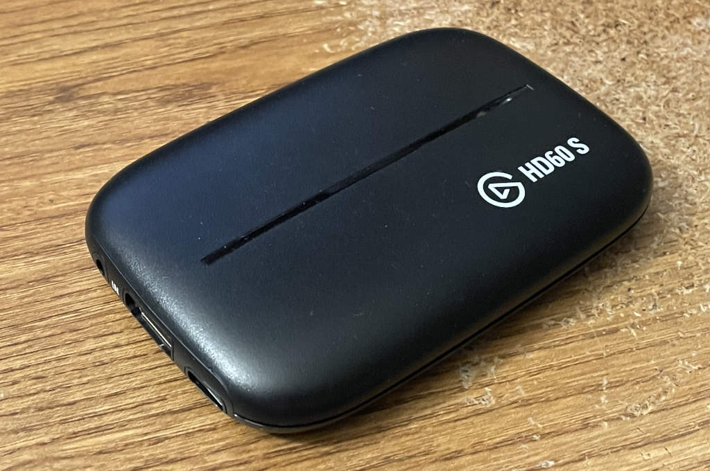
The videos inspired me. I thought, “I should totally try this!” So I went on eBay and looked for broken devices. I have a pretty decent understanding of how video encoders and decoders work, so I thought it would be a fun project to try to fix an HDMI capture card. I found a broken Elgato Game Capture HD60 S USB 3.0 device. The listing said that nothing happened when you plugged it in.
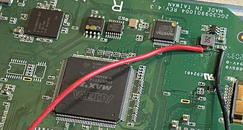
When it arrived, I was able to verify exactly what the listing said. Nothing showed up on my computer when I plugged it in. I cracked it open and had a look at what was happening internally when it powered up. I started by poking around at voltages on the board with it plugged in, and it was pretty obvious that something was dragging the power rails down. Little did I know at that point what I was getting myself into.
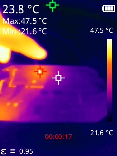
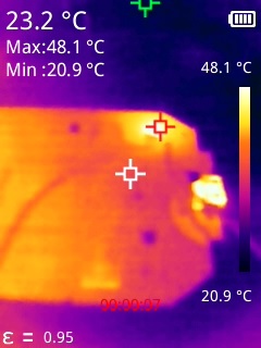
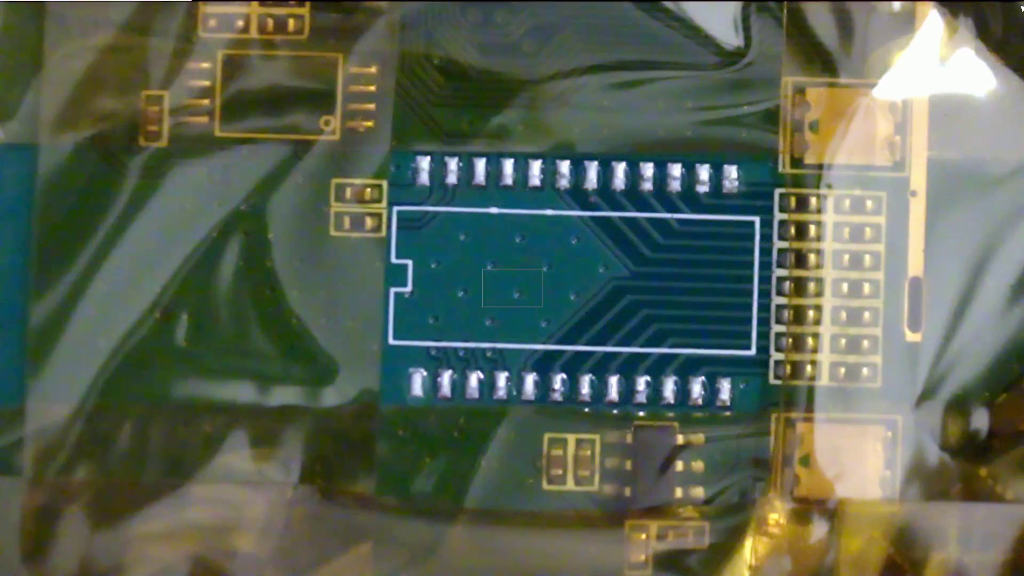
Honestly I could tell what was getting hot just by feeling around with my finger, but this was a good excuse to use my thermal camera to take some fun pictures.
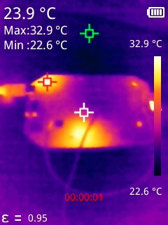
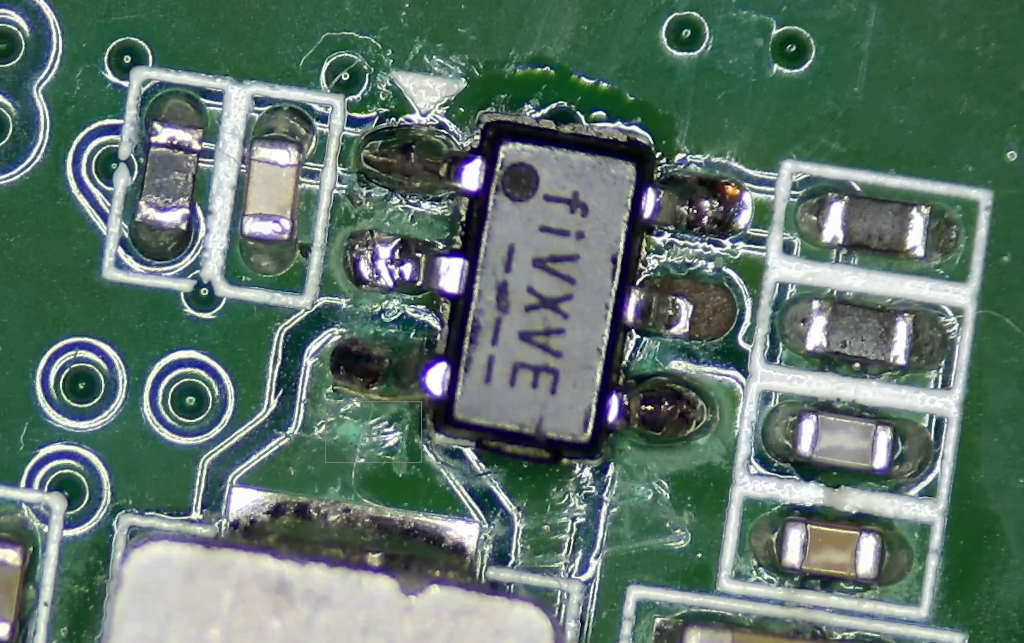
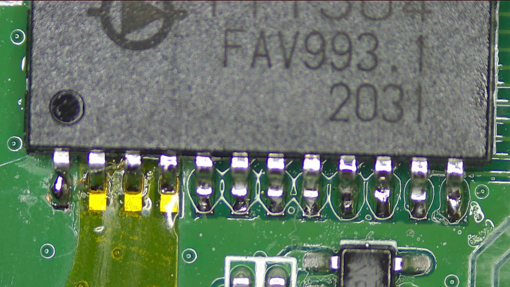
In this one, the red cursor indicating the hottest point in the image is pointing to a small chip in the upper-left corner of the board marked “fiVJVE”.
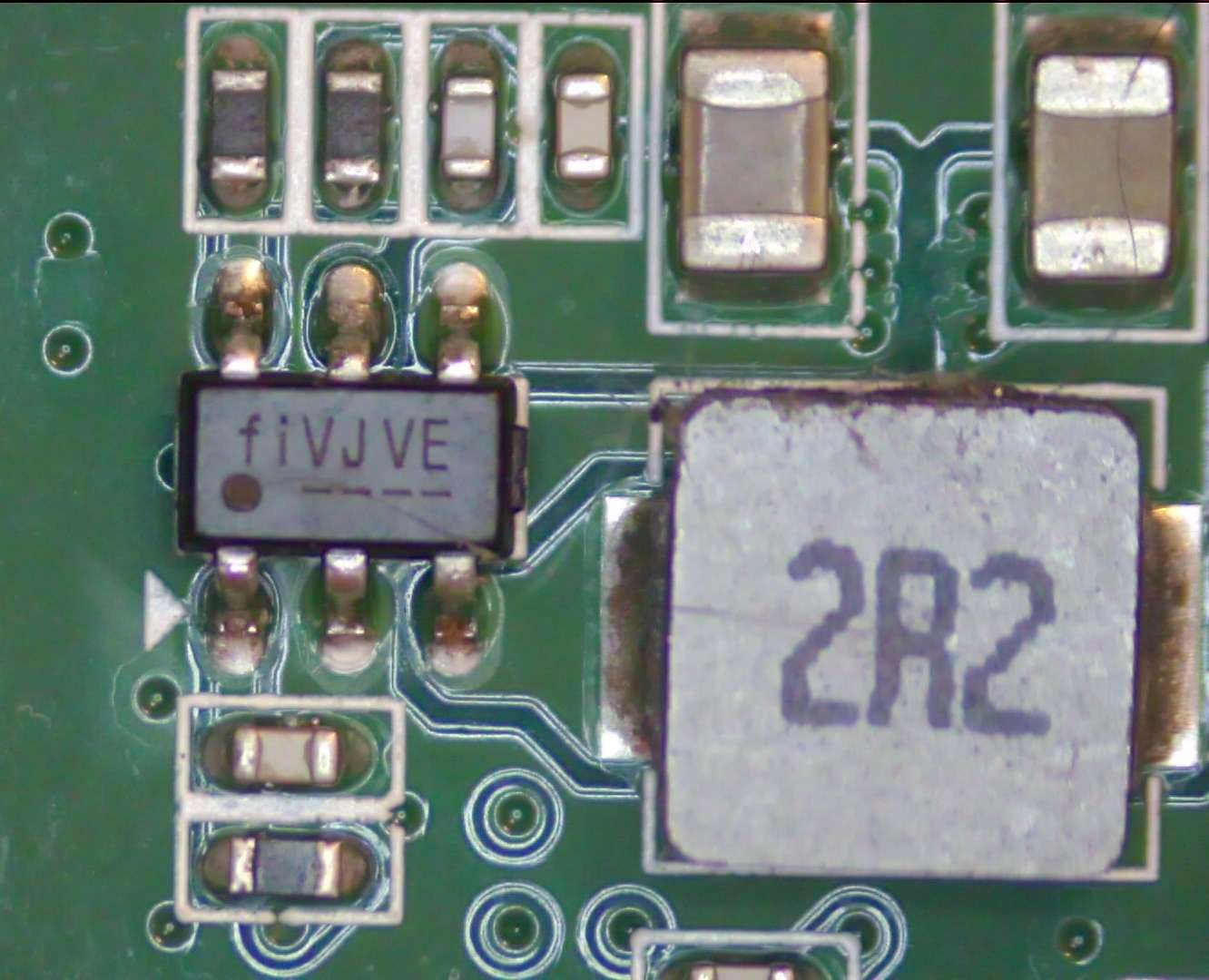
This was pretty clearly some kind of a switching regulator, which I concluded due to its proximity to the “2R2” inductor (meaning 2.2 uH). Measuring the pins, I could see 5V going in, but obviously something was wrong because the voltage at the inductor (the output) was far too low.
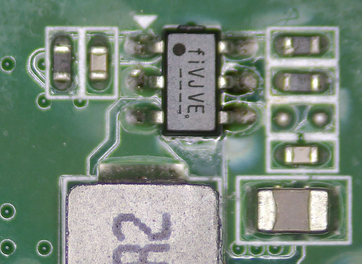
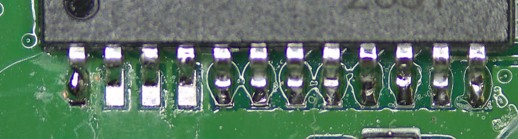
There was also another fiVJVE chip on the board, with a pretty much identical circuit next to another 2.2 uH inductor. The circuit was missing a component, but I was pretty sure it was normal because the solder blobs looked like they came that way from the factory. It wasn’t getting hot, but it was also putting out a low voltage so I suspected something was wrong with it too:
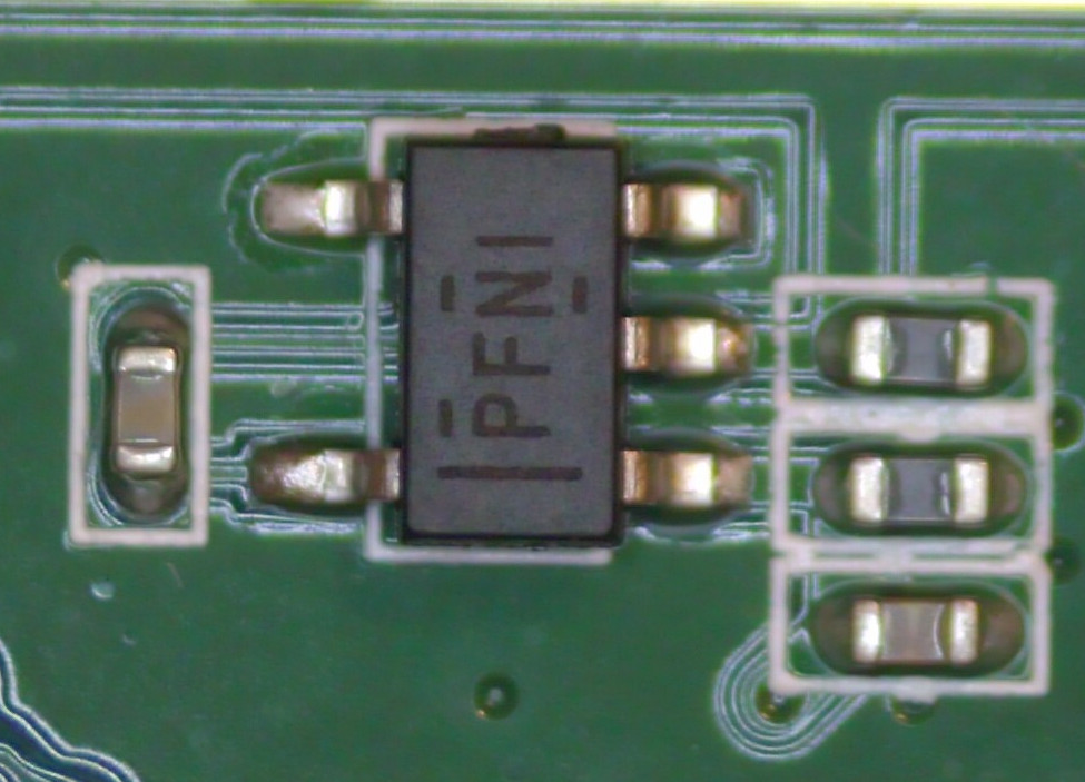
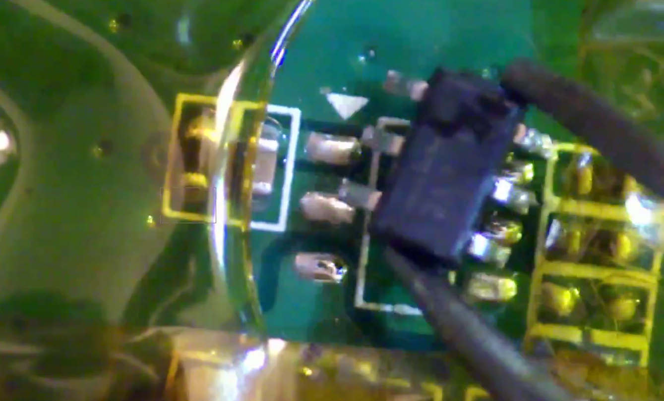
In the heat image above you can see another area on the board (near the bottom) that was also getting hot. It turns out it was actually originating from the other side:
Yeah, that’s my finger in the picture. It helped adjust the levels in the image so the chip that’s getting hot is easier to pinpoint. This chip was labeled PFNI:
OK, so what could I do with this information? I found two chips that were getting hot, and another chip that likely wasn’t putting out its correct voltage. I started out by trying to identify what they were. Small chips with markings like this can be quite difficult to figure out. Luckily, there are a few SMD marking code search engines out there. Searching smd.yooneed.one for fiVJ didn’t result in any exact matches, but it did point out that the code “fi” went with the Fitipower FP6121-IS9P. This led me to Fitipower’s website, where I saw they had a bunch of different chips. Using Google’s help I was eventually able to narrow it down to being the FP6373A.
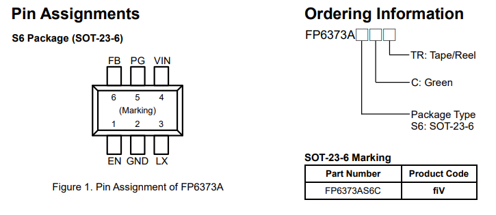
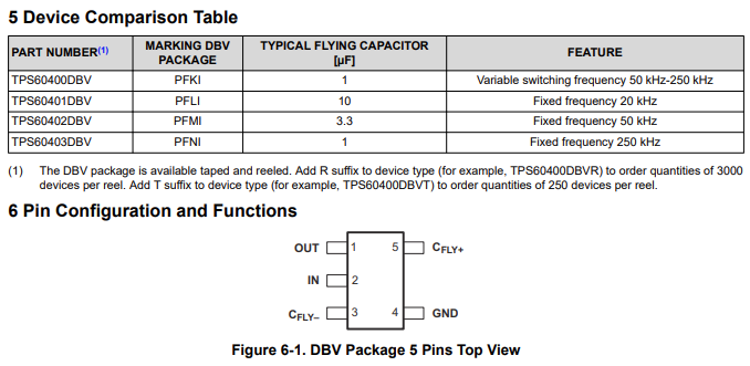
The pinout made sense on the board, and the fiV marking also matched. Yay! Now I had an idea what I was looking for. The PFNI chip ended up being even easier to identify. Google led me straight to the TI TPS60403DBV voltage inverter:
One thing in common with all of these chips is they were all taking in 5V for their input and I was measuring that their outputs all had a pretty low resistance to ground. I started wondering if maybe someone fried this device by somehow putting more than 5V into it. How they did that, I have no idea.
I wasn’t sure why the other FP6373A regulator wasn’t getting hot. It wasn’t putting out much voltage and nothing else was getting hot on the board, so I decided to try injecting voltage on its output power rail instead to see where the low resistance was coming from. I could deduce its correct output voltage because it was going to a Winbond W25Q32JVSSIQ SPI flash chip rated for 2.7 to 3.6V. I was pretty sure it was on a 3.3V rail. I soldered wires to the regulator’s output and ground and used my bench power supply to inject 2.7V into the circuit with a small controlled current that I could slowly turn up. The idea was that I could find what was getting hot on the board and determine what to blame for this power rail being bad.
This process pretty quickly revealed the FP6373A itself as the root problem.
I think maybe during normal operation when it was being supplied with 5V, it was putting itself into some kind of safety shutdown mode and killing its output power rail. The datasheet does mention overcurrent and overtemperature shutdown capability. When I injected voltage directly, the regulator couldn’t shut off the power rail so it had no choice but to get hot and announce “hey, I’m the problem!” through my thermal camera.
This was actually great. I wasn’t totally confident about whether the TI chip was to blame rather than something downstream of it, but since two other chips on the 5V rail were also fried, I thought a good first step would be to replace all three of them and see what would happen. Unfortunately the FP6373A isn’t available at the usual US distributors, but I was able to find it for sale on LCSC at $0.17 a pop, and the TI chip was conveniently also available there for $0.58. Would it really be this easy? Just replace three chips totaling less than a dollar in value, even in quantities of 1? The shipping and handling was orders of magnitude more expensive than just the parts themselves!
After the parts arrived from China, I was able to successfully replace them. I’m always paranoid about upsetting nearby resistors and capacitors when I’m using hot air, so I like to use Kapton tape to shield everything else.
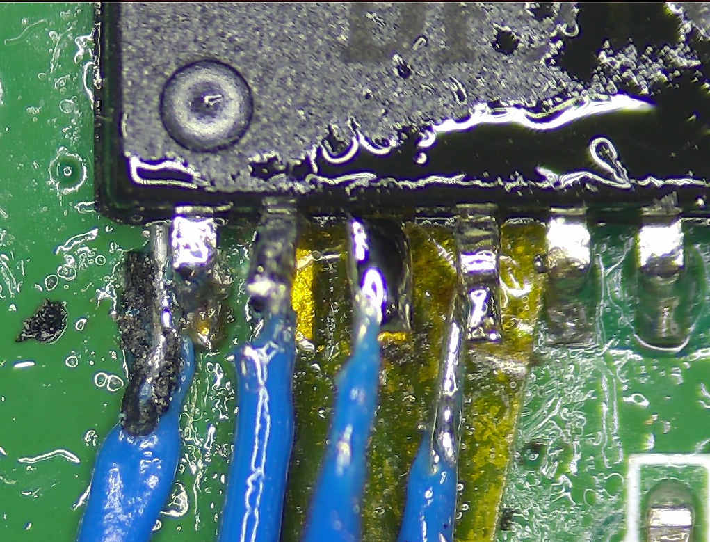
The process of soldering in the new chips was mostly easy, but the ground pins did soak up quite a bit of heat. I think this PCB design doesn’t have great thermal relief on the grounds. I did accidentally lift a pad for one of the regulators, but it wasn’t connected to anything (the “PG” signal) so there was no harm done. The fact that it wasn’t connected to anything was exactly why it was so easy to lift it. Also, the heat that the ground pin was eating up misled me into thinking I could use the same heat on the other pins.
In addition to my lifted pad (middle pin on the right), you can see here how much trouble I had soldering the ground pin (middle pin on the left). It really didn’t want to heat up. I probably could have heated the whole board to help my soldering iron out, but hey, it’s connected.
Anyway, after replacing all three chips, it worked! None of the new chips were getting hot, the HD60 S showed up as a USB device when plugged in, and it worked perfectly for capturing and passing through an HDMI signal. I was pretty excited to successfully fix it, but there was still a problem: none of the indicator lights worked. There are seven white LEDs and seven red LEDs, and they are supposed to do various things to tell you what’s going on. The white lights are supposed to blink twice when you first plug it in, for example.
This was a little deflating. I had kind of fixed it, but not really. Now what?
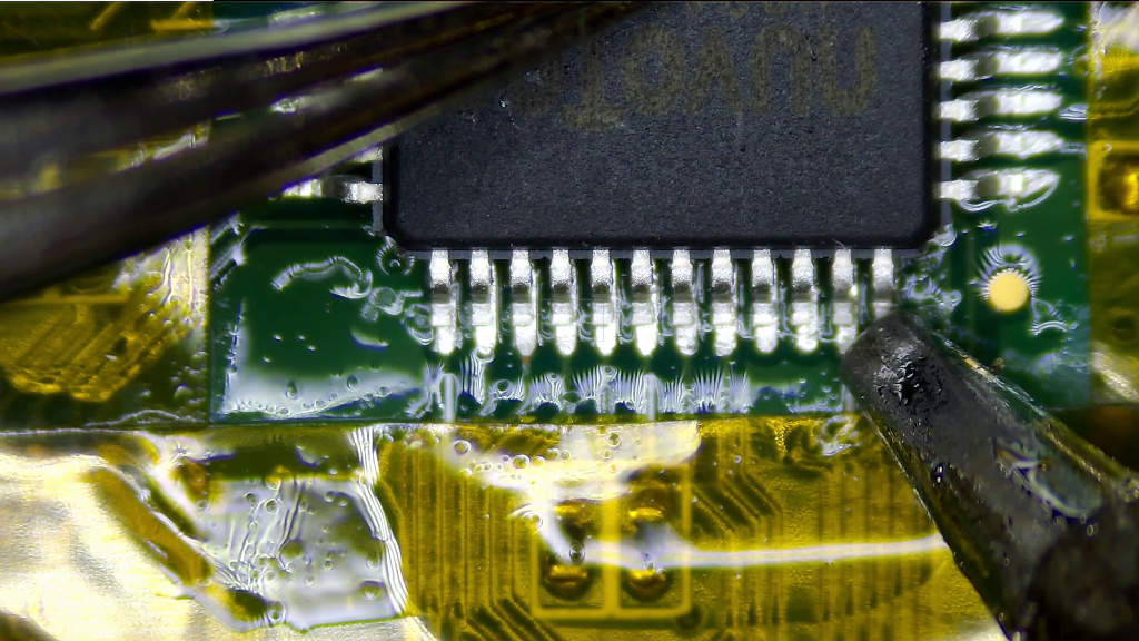
Back to the drawing board. I looked closer at the PCB to understand how the LEDs work. The relevant chip is the IT1504, made by Innochip. Looking further at its datasheet, it is a 16-channel LED driver chip. You talk to it with a serial data interface that appears to be very similar to SPI. It turns out a lot of LED driver chips from many manufacturers such as Toshiba and ST also use this same communication scheme. At first I though it was odd, but it seems pretty standard. It’s a variant of SPI where you send a particular number of clock pulses to choose which command you want to perform.
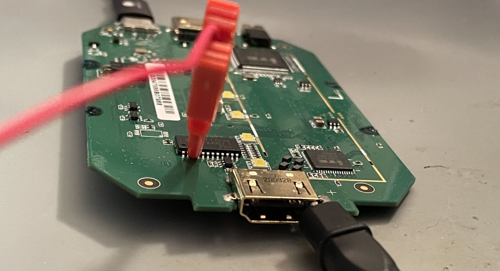
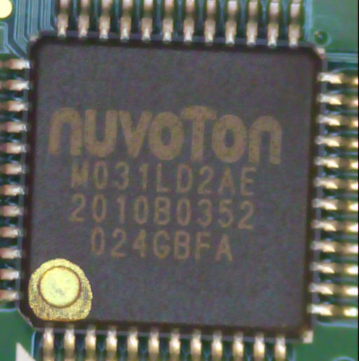
I monitored the relevant data input pins on the IT1504 using my oscilloscope, and I could definitely see some traffic being sent to it. By the way, I followed the traces and discovered that the IT1504 is being controlled by a Nuvoton M031LD2AE microcontroller, which is an ARM Cortex-M0.
The presence of SPI traffic here proved it was at least trying to do something, so I assumed that the LED driver chip was probably fried. That presented a pretty big problem though: how could I find a replacement for the IT1504? It wasn’t stocked anywhere. LCSC didn’t have it, and of course none of the US distributors had it either. I couldn’t even find any sellers on AliExpress or utsource.
I reached out to Innotech, who surprisingly wrote back the next day and kindly offered to send me a few free samples for the price of shipping, but then realized they only have full reels in stock so they couldn’t send me any samples. That was nice of them to check, but I definitely wasn’t going to buy a full reel of IT1504 chips just to fix this one problem.
This pushed me toward a huge search all over the internet for LED drivers to try to find a suitable equivalent replacement. The IT1504 datasheet I had access to didn’t include the full command info, so I wasn’t sure exactly what I was looking for. There were several discontinued parts from other well-known manufacturers that looked similar, but I wasn’t finding any exact matches. That’s when I discovered something really strange.
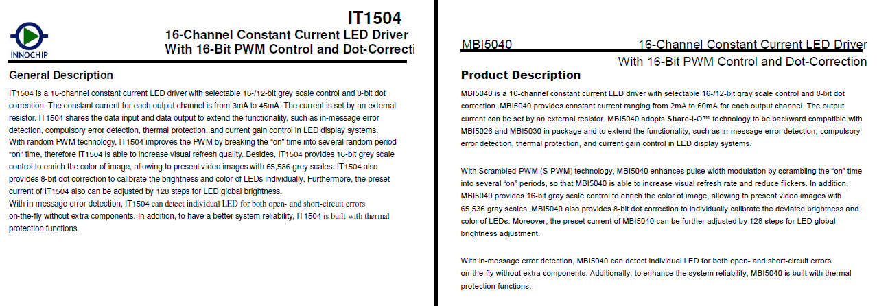
I somehow stumbled upon Macroblock‘s product offerings. Specifically, the MBI5040. The datasheet seemed to match up pretty well with the IT1504. In fact, a little too well. Here is an example of what I mean (click if you want it larger so you can read it):
Here are a few more side-by-side comparisons to really hit the point home:
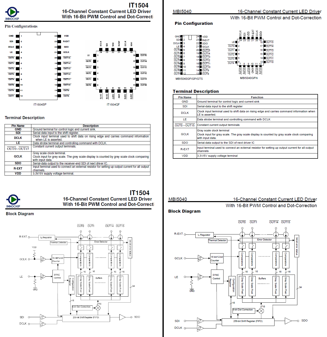
They’re almost exactly the same! Everything is laid out in precisely the same order. The current output specs differ slightly, but aside from that, they’re the exact same product, right down to having identical block diagrams. The wording has been tweaked here and there, but both of these datasheets are clearly from the same source. These companies are both based in Taiwan. Maybe one of them licensed the design from the other? Or perhaps there is some industrial espionage going on? There is definitely some funky stuff going on with the fonts on the Innochip datasheet’s general description page. It randomly switches around between serif and sans-serif. It’s the kind of thing you notice when you’re reading an email that somebody sent and you can tell they’ve obviously been copying and pasting while writing it. That doesn’t necessarily mean anything, but I thought it was weird.
Heck, even the part numbers are pretty much the same. If you pretend that the capital letter “I” in MBI5040 is really the number 1, you have MB15040 and IT1504.
I have no idea which product is the original here, but either way, this was really good news for me. I had successfully discovered another chip that would likely be suitable as a replacement for my assumed-to-be-fried IT1504. Additionally, the MBI5040 datasheet actually had command info, so if it came down to it, I could dive deeper and really try to understand what the SPI traffic was doing. I was able to find the MBI5040GF available for purchase on both AliExpress and utsource, so I bought a few.
Replacing the LED driver chip was a pretty simple job. Once again I used Kapton tape to protect me from myself.
I was feeling pretty good about my situation at this point. I cleaned up all the flux residue and anxiously plugged in the HD60 S to my computer.
Video capture worked fine, so I didn’t make it any worse, but the lights were still not working! What in the world? Next I started wondering if perhaps the LEDs themselves were broken. I rigged up my bench power supply and a resistor so that I could pass current through them (without the whole device powered on, of course), and the LEDs all tested out fine physically. I was able to light each one up.
I was totally out of ideas at this point. A brand new chip didn’t fix it, and the LEDs were known good. That’s when I started searching on Google and found something shocking: apparently the LEDs going out on these Elgato HD60 S capture cards is a known problem that multiple people have experienced. In particular I found two different Reddit posts with four unique users complaining about running into this same problem:
- https://www.reddit.com/r/elgato/comments/pcvtqj/why_doesnt_my_elgato_hd60s_light_up/
- https://www.reddit.com/r/Twitch/comments/qfdxuu/elgato_hd60_s_can_anyone_help_me_with_this_issue/hhzsvez/
Not only that, but sometime during this whole saga I also bought another “dead” HD60 S on eBay that turned out to work fine but had the exact same LED fault. It was starting to look like this indicator light failure was actually quite common!
So yeah. It’s very likely that the LEDs on this one weren’t working even before the voltage regulators originally got fried. This led me to a new bonus challenge: Could I figure out why the LEDs didn’t work and fix them? After all, I now had two different units both experiencing this failure and I knew of at least four other people with the same problem. If you go to the parent post at the second link above, there’s a video that shows how the white LEDs are expected to flash twice when you first plug it in.
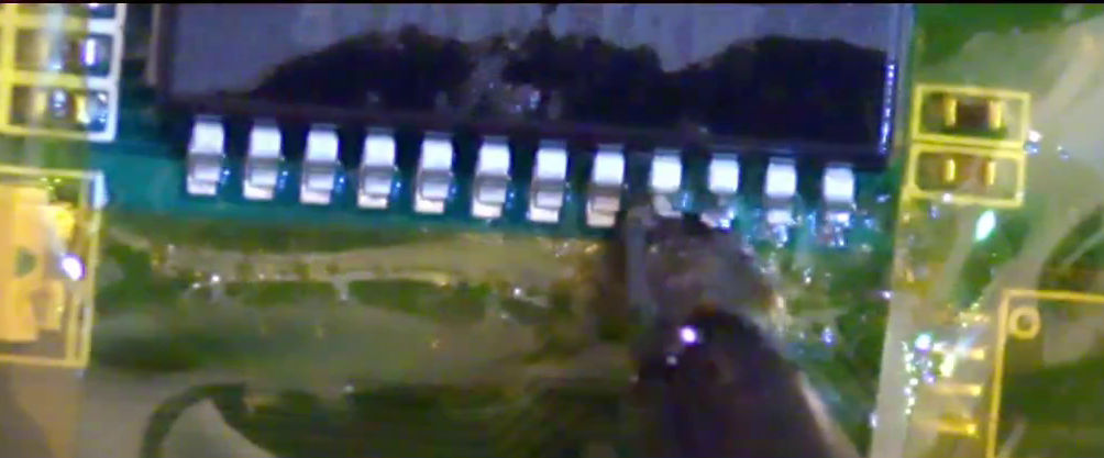
My first idea was to verify that the actual LED circuitry on the board was functional. To perform this test, I lifted the relevant SPI input pins on my replacement MBI5040 LED driver and soldered wires to them, as well as ground:
This allowed me to rig something up with a Raspberry Pi Pico to manually control the LEDs by sending the appropriate commands as documented in the MBI5040 datasheet. I’ll let this picture speak for itself:
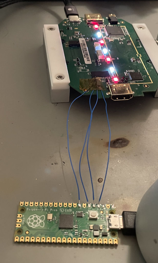
It was at this point that I became very confident there was nothing physically wrong with my repaired HD60 S at all. I could perfectly control the lights with my Pi Pico, so the circuit was fine. The Nuvoton Cortex-M0 microcontroller was simply never deciding to turn them on.
This whole MBI5040 replacement story was all for nothing! I was so proud of myself for finding a suitable substitute IC, but it was all mostly just a big waste of time. The original chip was probably fine all along. I decided to confirm that theory just to be sure. I put the original IT1504 chip back onto the board. In order to avoid having to bend pins, I covered the 3 pads that I wanted to avoid soldering to the chip with Kapton tape. This kept them insulated, and then I just soldered all of the other pins normally.
Then I resoldered the wires and repeated the experiment with the Pi Pico. No surprises here — the original chip was totally fine too. After I was done tinkering, I simply pulled the Kapton tape out and then was able to solder the remaining 3 pins normally. I thought this solution was pretty clever and saved me some time! Here’s a view after I pulled out the tape, but before I soldered them down.
And yes, I know pin 1 looks messy. Once again, it’s a ground pin and I guess they didn’t add thermals on the ground pins on this board. It was a pain to solder. I fixed it up afterward though.
So yeah. The original IT1504 chip worked fine. I was a little annoyed, but this side quest wasn’t entirely a waste of time. Getting ahold of the MBI5040 datasheet importantly gave me a perfect reference for how the LEDs are controlled by software. It was looking more and more like this was a software problem as opposed to a hardware problem. I was invested in this problem at this point. I couldn’t give up now!
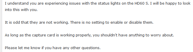
I began the next phase of this project with a simple idea: ask Elgato if there is some kind of known issue with the status lights. Maybe there was a setting I was missing that allowed you to disable them. Essentially, they politely told me to take a hike:
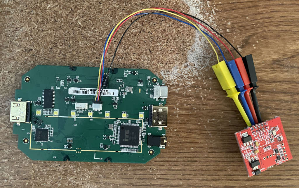
That’s okay. I felt like solving it on my own anyway. I decided to focus on understanding what was going on in the firmware running in the Nuvoton M031LD2AE microcontroller. By a stroke of pure luck, I had gained some experience last year with Nuvoton MCUs when working on my Mac ROM SIMM programmer. I already had a Nu-Link2-Me that was bundled with the dev board I bought for that project. The next step was to figure out how to access the programming pins on the microcontroller. It turns out that there are a couple of small JST connectors on the board: a 4-pin one and a 6-pin one. Tracing out the pins one by one, it quickly became apparent that the 4-pin JST connector was for programming the MCU! I hooked it up using the only 4-pin JST cable I had on hand, which had grabbers on the other end.
I didn’t check, but I think it’s a pretty good educated guess that the 6-pin JST connector next to it is for programming the Altera MAX II CPLD that is also on this board. It just makes sense.
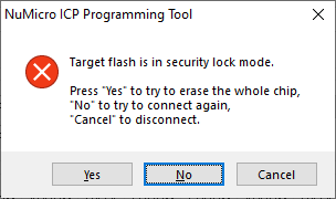
I didn’t care about the CPLD though. I tried to read the firmware out of the Nuvoton chip using NuMicro ICP Programming Tool, but of course Elgato protected the contents:
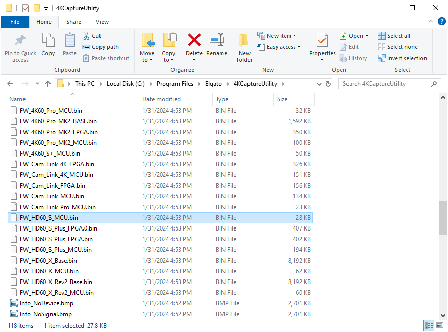
Never fear, though. It turns out that Elgato includes the latest firmware with their 4K Capture Utility:
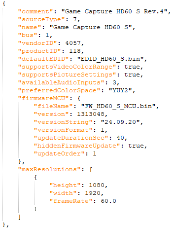
Reading the included ElgatoDeviceCapabilities.json file in the same folder also provided some insight. This firmware is specifically for the version of the device with USB product ID 118 (0x0076), which definitely matches mine. Elgato refers to this device as the “Game Capture HD60 S Rev.4”:
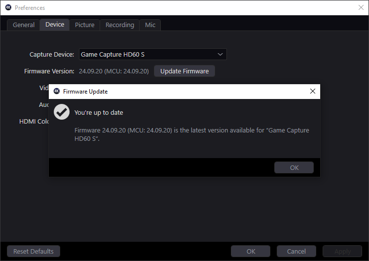
The firmware was already up to date when I checked in the 4K Capture Utility. You can also control-click the settings icon to enable an Update Firmware button, but it did nothing because the newest firmware was already installed on it:
This was great though! The FW_HD60_S_MCU.bin file looked very much like a normal Cortex-M0 firmware binary. You can tell by looking at the start of it in a hex editor. The very first 4-byte word should be the initial stack pointer, so something in RAM. Then following that is a bunch of interrupt vectors including the reset vector.
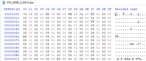
This all checked out. 0x20000E70 looks like a valid stack pointer, and each 4-byte word following that looks like a valid flash address. It looks exactly like a Cortex-M0 vector table. I loaded it into Ghidra and also used SVD-Loader to try to map out some of the registers. I had to modify the SVD file (M031AE_v1.svd), which I got from the NuMicro_DFP pack on keil.arm.com, to get it to load with the plugin. Apparently it doesn’t like if you have multiple addressBlocks per peripheral, so I modified the first one in each peripheral to contain the full range of addresses.
And thus began the humongous effort of trying to figure out what this little MCU was actually doing.
The SVD file helped me identify the various peripherals being used: mostly GPIO, a timer, and I2C. Nuvoton’s M031BSP project was very valuable for identifying a ton of functions. I did it by hand, which was probably slightly insane, but I wasn’t sure what compiler had been used. Since I knew which pins were hooked up to the LED controller chip, I was fairly quickly able to identify functions that control the LEDs. It was hard to understand their purpose in the grand scheme of things though. Sometimes they were buried deep inside multiple layers of function calls.
Knowing that I2C was being used was very helpful, because I saw there were other chips onboard that would communicate through it: the ITE IT6802E and IT66121FN. The IT6802E is an HDMI receiver. I don’t have any detailed documentation for it, but I’m pretty sure it converts an incoming HDMI signal into a parallel data stream suitable for the capture portion of the device to read in. The IT66121FN is the opposite. It takes a parallel data stream and sends it out as HDMI. This would be necessary for the passthrough functionality, providing an HDMI output signal to go through to your TV or monitor.
Anyway, I found some ITE driver code in some random GitHub projects such as this one, which quickly helped me identify a bunch of functions and variables as belonging to ITE’s drivers. This helped me gain a better understanding of what was happening in the firmware. I actually spent way too much time on this, but I think it was useful in the long run. Plus, it was good practice with Ghidra.
Once I had a good idea of the overall structure of the firmware, I decided to try figuring out how I could debug the code. The chip was protected, but I figured that I should be able to erase it and reflash the firmware. To be safe, I desoldered the original M031LD2AE chip and put a new empty one onto my board instead. They only cost $1.14 on Digi-Key in quantities of 1. Why not?
When I flashed FW_HD60_S_MCU.bin onto my brand-new blank chip, it definitely worked fine, but it re-protected itself so I couldn’t do any debugging! The offending code was pretty easy to find in Ghidra. There’s a function that is called to update the config registers with the proper locked state as well as the number of 512-byte data flash pages to reserve from the application ROM.
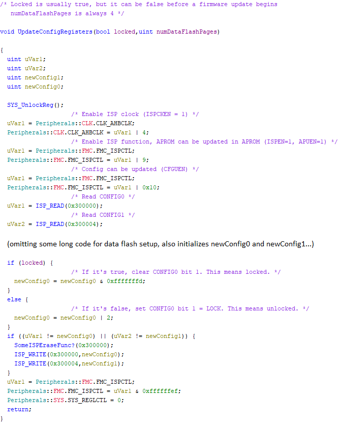
I simply had to hack this function to always leave the chip unlocked. Then I reflashed the chip and I was finally able to debug the code! I inserted some breakpoints and stepped through the initialization code with OpenOCD and GDB to figure out why the LEDs weren’t being controlled. I found some places in the code where LED control would happen, but they were being skipped. I decided to force the code to run by filling in register values and RAM in GDB, and sure enough, I was able to at least force the lights to turn on. So clearly the code was there to control the lights, but it wasn’t running for whatever reason.
This chip unlocking mess led me down another rabbit hole. I assumed that the original Nuvoton MCU I removed had some other protected contents like a bootloader, so I decided to see if I could extract it by installing my new unlocked firmware file as an update through Elgato’s software. The idea was that after my new unlocked firmware was installed, the protection would be disabled and then I could read out the entire contents with my Nu-Link2-Me. Why would I want to do this? Well, it would just be nice to have as a backup in case I screwed up one of the chips, plus the bootloader might contain other clues.
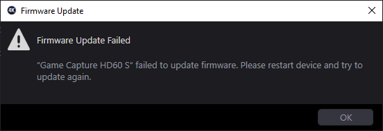
I tried it out on my other HD60 S with broken LEDs which still had its stock Nuvoton MCU fitted. This required modifying ElgatoDeviceCapabilities.json to point to my unlocked firmware. I also had to change the version listed in this same file so that it would think it was out of date. After making these changes, the 4K Capture Utility allowed to install my new firmware through the normal firmware update mechanism. The utility did tell me the firmware update failed after it finished (more on that later).
This totally freaked me out because it appeared to brick the device. It didn’t work as a capture card anymore. But luckily, but I was left with an unlocked chip, just as I had hoped! This allowed me to read out the rest of the content of the flash that had previously been protected, including the LDROM (containing Elgato’s first-stage bootloader), data flash contents, and the correct original config register contents. This was really exciting because it meant I now had everything I would need in order to completely program a brand new Nuvoton MCU to contain Elgato’s stock firmware, including their bootloader. I rewrote the original Elgato firmware back to this second HD60 S’s APROM (application ROM) using Nuvoton’s tools, and re-locked the chip. Thankfully, this fully restored it to working order — except for the LEDs of course.
I also disassembled their small LDROM bootloader that I was able to read out of the chip, but it wasn’t really anything exciting. It receives commands and data over I2C and is capable of reflashing the APROM. Interestingly I discovered that if the chip is set for unprotected mode, the bootloader actually waits around for update commands instead of booting the application firmware. So Elgato is using the locked/unlocked bit as a way of signifying whether it should stay in the bootloader or not, which I find to be a little bit weird. That completely explained why my second HD60 S stopped working after I installed my unlocked firmware — it was stuck in the bootloader waiting forever because the chip was unprotected.
Anyway, I’ve really started to ramble on about things unrelated to the LED problem. Let’s get back on track. The point I’m trying to make here is that I was able to read out all of the stock microcontroller contents, which gave me the confidence I desperately needed in order to start tinkering even further to figure out the LED problem. I was kind of stuck at this point though. Why was the Nuvoton chip not controlling the LEDs? Some of the LED control happened over I2C from something else, so I was beginning to worry that the actual problem was once again at a different level.
Fortunately though, I was gaining a better understanding of the architecture of the entire product at this point. Here’s a broad overview of how it works:
- The main Cypress/Infineon CYUSB3014 USB 3.0 peripheral chip, which I haven’t mentioned until now, is an ARM926EJ-S. It sends commands to the Nuvoton MCU over I2C. This is the chip that actually communicates with the host PC through the USB 3.0 port.
- The Nuvoton ARM Cortex-M0 microcontroller sets up and monitors the ITE video receiver and transmitter chips through a separate I2C bus.
- The Nuvoton MCU also controls the LEDs.
- The Nuvoton MCU communicates status information back to the CYUSB3014 through I2C.
- The CYUSB3014 receives the video data stream from the IT6802E (likely through the MAX II CPLD, putting it in a format suitable for the CYUSB3014 to grab) and sends it to the computer over USB.
I thought I would take a break from the Nuvoton chip for a while and start trying to understand the main Cypress processor instead. Yes, as I just mentioned above, there are two different ARM processors working together to implement the video capture functionality. Fortunately, Cypress/Infineon also provides a free SDK for these USB chips. The firmware is stored unprotected in the Winbond W25Q32JVSSIQ flash chip that I talked about very early on when I thought this was purely going to be a hardware repair project.
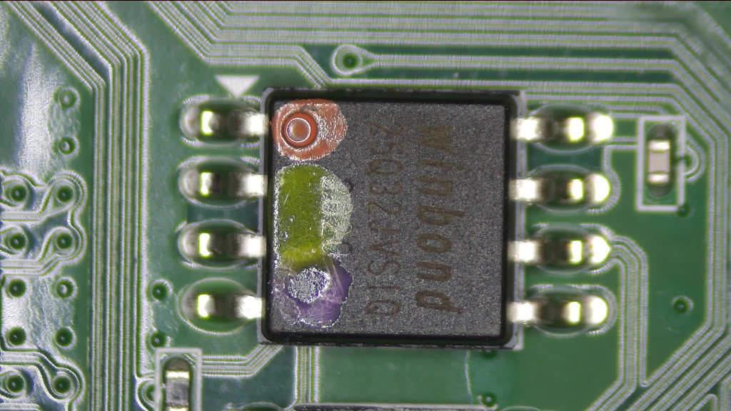
I desoldered the SPI flash chip and read it back using a programmer. It’s a 4 MB (32-megabit) chip. I also tried to do it in-circuit without removing the chip first, but I didn’t have any luck. I even accidentally knocked a small 0402 0.1 uF decoupling capacitor (seen above on the right) off the PCB while I was trying to clip onto it. Luckily the capacitor wasn’t damaged and I was able to put it right back on.
After dumping the chip contents, I used it to start trying to work my way through understanding what the CYUSB3014 was doing. I was able to use Cypress’s existing SDK binaries to help identify a lot of the functions in the dump. It turns out that the Cypress SDK uses the ThreadX RTOS under the hood.
I really didn’t want to dive deep into this firmware to the same level that I did for the Nuvoton chip though. I was already worn out from that disassembly. At the very least, I was able to see that the Cypress chip sends commands over I2C to the Nuvoton chip.
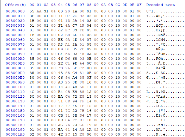
Looking through the rest of the SPI flash dump, I could see that starting at offset 0x300000, there were a bunch of small data chunks that looked like little pictures. Here’s an example:
I couldn’t figure out why there would be little pictures in the flash chip here. What would the purpose be? It made me wonder if maybe it was some kind of small icon, since I’ve seen similar data for icons while analyzing old Mac ROM dumps. Given the context of this blog post, you might be screaming at me right now telling me what this data obviously is, but at the time I was totally oblivious.
I ended up solving this mystery as soon as I started looking into what was going on with five unknown GPIO pins in the firmware on the Nuvoton chip. There were a bunch of functions that controlled these pins, but I wasn’t sure what they did. I traced them out on the PCB and discovered they were going to a Diodes Incorporated PI5C3257 quad 2:1 mux/demux bus switch.
This was the magic discovery that finally unblocked me. This bus switch is being used to decide whether the CYUSB3014 chip or the Nuvoton microcontroller should be wired up to the SPI flash chip. Prior to this moment, I thought that the SPI flash was entirely dedicated to the CYUSB3014. In reality, the Nuvoton microcontroller takes over control of the SPI flash after the CYUSB3014 has finished booting. This enabled me to disassemble a bunch of new functions which were all related to bit-banging SPI transactions, as well as higher-level functions for SPI flash chip erasing/reading/writing.
A light bulb went off in my head. Yes, these chunks of data in the flash chip were pictures! But not in the conventional sense. They were describing the various LED animations. Each set of 16 bytes is an animation frame written to the 14 LEDs. In the example above, a single red LED turns on and six of the seven white LEDs do stuff. The last two bytes in each row are a delay time before moving onto the next frame. The first 16 bytes looked kind of weird though. They looked like they possibly contained some header data for the animation or something.
I also found some code that was reading data from the start of the 0x300000 section, but in my SPI flash dump that section was pretty much completely empty:
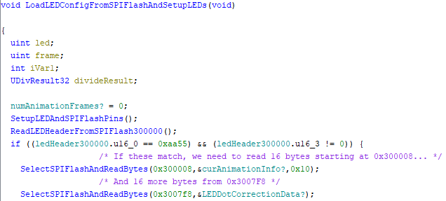
Everything was starting to make sense. There was a check in the Nuvoton MCU firmware to see if the first two bytes contained the 16-bit word value 0xAA55:
In my dumps of the SPI flash chip contents from my units with nonfunctional LEDs, that section of the chip was empty. It was programmed as all 0x00. The firmware was bypassing all of the LED control code because expected data wasn’t stored starting at 0x300000 in the flash chip! I confirmed this data was missing on both of the HD60 S devices I was testing with.
Unless I wanted to go overboard trying to figure out how to artificially populate all this data from scratch, I had no choice but to buy a third HD60 S that was confirmed to be fully functional. That’s what I ended up doing. Unfortunately it was an older revision and had a completely different PCB, but it was still based on the CYUSB3014. It also used a Nuvoton microcontroller, but it was a different model. It still had an IT1504 for LED control though, as well as a Winbond SPI flash chip, so that was promising.
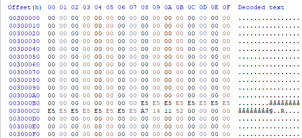
I confirmed that its LEDs worked fine, and then I dumped the SPI flash. By this point, I had figured out how to dump the flash contents without any soldering by forcing the CYUSB3014 to boot over USB (removing a jumper on the board) and then uploading a Cypress-provided RAM bootloader capable of dumping the SPI flash (cyfxflashprog.img), but I don’t want to stray too far from the LED issue at this point. Here’s the start of the good data at 0x300000:
Okay, that data makes way more sense. The first 16-bit word (little-endian) is 0xAA55 just like the firmware was looking for. It also has a bunch of other header data, indicating there are 26 different LED animations, and including info about whether they are even animations at all. To be honest, I haven’t figured out what every piece of this data actually means, but each animation has a 16-byte summary. They start at 0x300008. I think the last 4 bytes for each animation are probably a CRC-32 of something.
Also, if you noticed in the original chip dump, there was a section starting at 0x3000B8 with a bunch of 0xE5 bytes. This is the dot correction data that gets loaded into the IT1504. Based on the decompilation above, it’s actually supposed to be at 0x3007F8, which is exactly where it is in the good dump:

The 0x521114A7 that follows is a CRC-32 of the preceding 16 bytes of data.
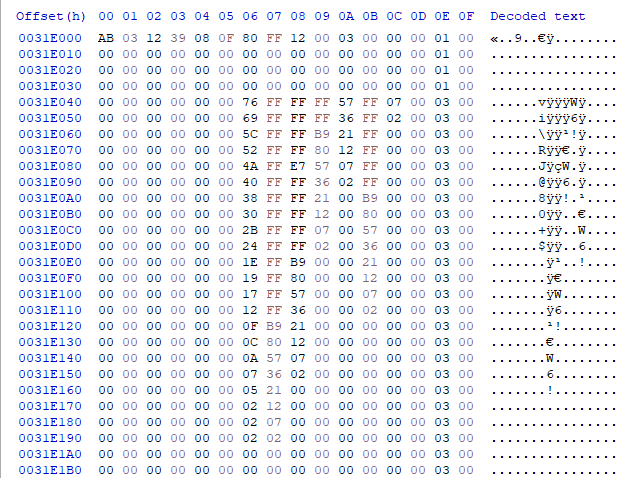
Further inspection revealed that the data in the SPI flash of the broken devices differed quite a bit. In fact, they were different from each other as well. This led me to believe that the animation data was probably corrupted in them. For example, here’s what the animation at 0x31E000 looks like in the good HD60 S’s dump:
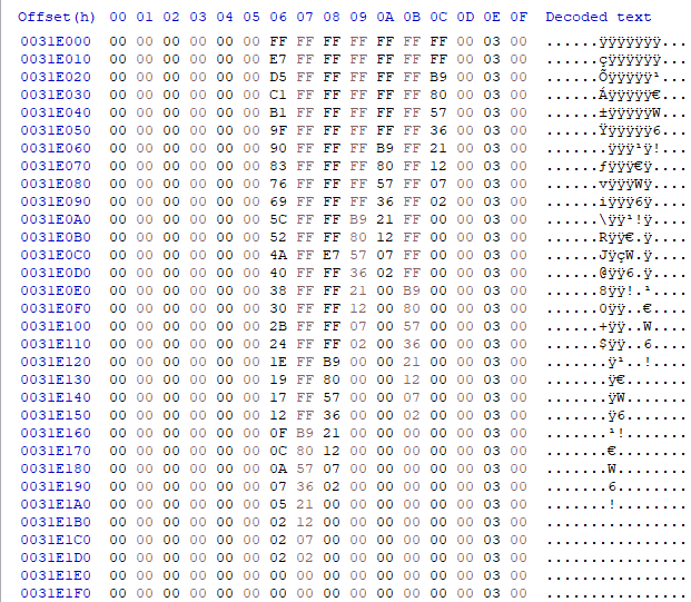
Notice how there is no weird header at the top like the original “picture” I was inspecting from one of the other dumps? It just immediately starts with animation data that is consistent with the rest of the nearby data. It’s also longer. This data makes a lot more sense. On the other hand, it was corrupted in two completely different ways in my two HD60 S devices with nonfunctional LEDs.
Several (but not all) of the animations in my nonworking devices started with a weird “AB 03 12 39” header. I don’t think the header is supposed to be there. Maybe there was a bug in an update procedure or something? The Nuvoton firmware indeed has functions capable of erasing and rewriting data to the SPI flash chip. I’m wondering if that code ended up running and somehow destroying the original contents.
You may be able to guess what I did with this new knowledge. I took the original SPI flash contents from the two devices with nonfunctional status lights, and simply replaced all the LED data starting at 0x300000 with the data from the working one. Then I flashed this new “hybrid” image to the non-working devices. Oh, I should point out that each device has its own unique flash dump. The USB serial number is embedded in there somewhere. So I preferred to preserve the data from 0 to 0x2FFFFF for each individual device.
I wasn’t entirely sure what to expect by trying this. The good SPI flash data came from an older revision of the product with a different Nuvoton microcontroller, but it sure looked like it matched what the newer firmware was looking for.
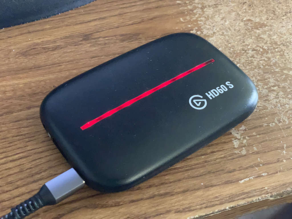
Here’s a picture of what I saw as soon as I powered one of the problematic devices after I reflashed its SPI flash chip:
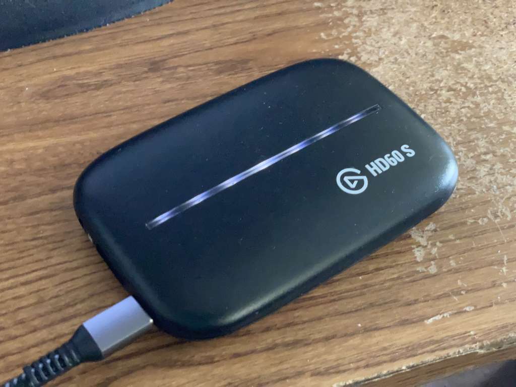
It freaking worked. The white lights flashed twice, and then the red lights briefly flashed once.
I think the red flash just means the signal was lost, because it also does it every single time I unplug an HDMI source from it. The older model doesn’t do this red flash on every powerup, but maybe it’s just a firmware difference about whether it should say “signal lost” immediately at startup with nothing plugged in. I’ve seen some mention online of red lights meaning that the signal is HDCP-protected, but I think that’s a different longer red blink which I’ve also seen when I first plug in my iPhone as an HDMI source.
I’ve also noticed that some of the animations that Elgato says it should do, like when I start or stop recording, don’t play on this newer model, even though they work fine with the older model. I haven’t been able to figure out if this is just a known difference with how the newer model works. I may try to get a good SPI flash dump of the correct LED animations from a newer matching model to confirm it for sure, but I have a feeling the animation data will be identical.
I also recently realized that the raw data for each animation is sitting around in C:\Program Files\Elgato\GameCapture\Animations if you have the older Game Capture utility installed, or /Applications/Game Capture HD.app/Contents/Resources/Animations on Mac.
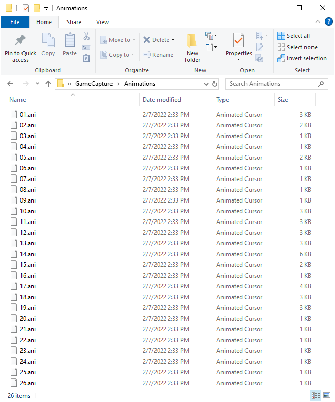
Looking through each file (01.ani, 02.ani, etc.), it looks like the animation data perfectly matches my dump of the older working device. The bytes for each LED are out of order, but if I reorder them correctly, I can create an identical copy of all of the animation data that I extracted from the good flash chip.
Since those animations live inside the Game Capture app (or next to it), it seems as though the software has the capability to load them into the flash chip. I wonder if that explains how the stored animation data ended up corrupted in the first place. A botched update perhaps? That would make sense to me. Maybe they disabled the ability for their software to upload them after they discovered it was screwing up people’s devices? It might be interesting to disassemble the Windows and/or Mac software and try to figure out how to convince it to directly upload the animations, but I’m honestly out of motivation to do that at this point. It looks like LedCtrlDll.dll might be an interesting file to look at if anyone else is hooked enough to continue diving deeper. It contains classes with interesting names like Ub530LedSpiRom and I2cIO_Ub530. Some quick disassembly in Ghidra indeed shows it creating a 0x80C-byte array for the header data that would go into the flash chip at 0x300000, and populating the contents with the dot correction data.
One last thing I noticed is if I do a firmware update of the HD60 S inside of Elgato’s 4K Capture Utility in Windows, it doesn’t wait long enough. It seems to work fine on Mac, but Windows has some issues. The firmware update is still in progress when it tells me that it failed. If I sit there and wait, eventually the lights flash on the unit and it successfully reboots into the new firmware. If instead I unplug it quickly after Elgato’s software tells me the update failed, I end up with an incomplete flash. I wonder if this has fooled people into bricking their devices? Especially if the status LEDs don’t work at all. I was able to successfully fix this problem by increasing the updateDurationSec in ElgatoDeviceCapabilities.json from 40 to 80. I get the feeling Elgato’s firmware update functionality is a little flaky, at least on Windows. In Elgato’s defense, they specifically recommend not to update firmware on the HD60 S unless their tech support tells you to. And they hide the functionality behind a special key combination when entering the settings screen.
I would like to figure out a way to share how to easily fix the LEDs for anyone else who runs into this problem, but the process is admittedly quite convoluted. It requires you to begin a firmware update (modifying ElgatoDeviceCapabilities.json to even allow you to install an update in the first place) and immediately unplug the device — otherwise the Nuvoton MCU takes control of the SPI flash, and you really need the Cypress chip to be in control in order to reflash its contents. Then, you remove the jumper on the PCB (instructing the Cypress chip to boot from USB), upload cyfxflashprog.img to RAM using download_fx3, and use a modified version of fx3_spitest to download the entire SPI flash contents and replace it with your patched LED section. Those are tools from the CYUSB3014 SDK. Finally, you unplug it, put the jumper back in, plug it back in, and perform a normal firmware update in 4K Capture Utility to restore the firmware back to the Nuvoton chip. You ignore the update failure message and wait another minute or so, and eventually it boots back up with working LEDs. If there ends up being enough interest in recovering these things, it might be possible for me to throw something together to automate the process, or at least provide binaries for everything. It would also be nice to figure out how to use Elgato’s software to directly reprogram the LED animations. For now though, I’m just going to sit back, relax, and celebrate my victory on this!
So in conclusion, yes, it really was that simple. All I needed to do was replace three chips for a total of less than $1 to bring this thing back to life. Every bit of extra time and money I spent on this project after that was all about figuring out a well-known indicator LED problem that really had nothing to do with my actual repair. I put way more effort into this than I should have, and yes I am probably a tiny bit crazy for actually doing this, but at least I now have an answer and fix for why the LEDs don’t work on some of these capture cards. It’s some sort of software/programming/update bug. I’m not sure which. Way to go Elgato!


thanks for documenting this rabbit hole. you had me sucked in at the SMD search and quickly finding a travelogue of my own hobbies.
First the innocent “I recently started watching fix it videos” and then this hell of a story. Thanks for sharing.
And now I realize, that I also followed your Chumby kernel adventure and I am no länger surprised about the depth of your knowledge.
Thanks again.
Really good read, thanks for the amazing effort in documenting all this too.
Great article!
I think this stuff just shows how firmware isn’t this magical code that is totally perfect and written by geniuses. Lots of smart people work on these things, but we are all flawed. Things like the failure message appearing too early, or the bootloader simply sitting in a loop waiting for commands. This is abundant in firmware and so fun watching you dig around and find these!
Brilliant!
Thanks for the trip down rabbit hole. I’m a sw engineer just learning to dabble in hw. If you ever consider summer reversing camp, I’m in.
You are a hero!
Thank you all for your kind comments! I have another fun “repair parts sourcing” story I plan on telling on this blog soon. It’s definitely not as involved as this one, but it was still another fun learning experience.
As someone who works on firmware for a living I can confirm that it’s definitely never magical, perfect code 🙂
This situation just keeps getting better and better. I tried to buy a fully operational HD60 S newer model with good LEDs on eBay so I could compare SPI flash dumps, but apparently “fully operational” on eBay means “everything works except the LEDs”.
That’s right, I now own a third newer unit from eBay with the exact same LED failure! Its SPI flash LED section is also corrupted. And of course, I brought its LEDs back to life the exact same way I fixed the previous two. Does anyone out there actually have an Elgato HD60 S revision 4 (USB PID 0x0076) with working status LEDs? I’m starting to wonder…
Maybe I should open up my own Elgato HD60 S service center!
This is an amazing post- it ties so much together, and you weave things together really well.
Thanks so much for sharing this with everyone!
What a great read, thanks from Sweden.
This is a better read than fiction 🙂
This is one thorough and well documented repair. Well done!
Thank you all! I’m still trying to figure out if my repair is 100% “correct” but I haven’t been able to find a newer model HD60S with working LEDs so I can compare the dumps.
Cracking Job mate. Very well done, and thank you for the mention 🙂👍
Thanks BuyItFixIt! I’m honored that you got to see my fix. Love your videos, keep up the great work!
As an update, I just fixed yet another one. It was sold as having a problem with being recognized as a USB 2.0 device, but when it arrived it didn’t have that problem at all. Maybe the original seller had a bad cable or port on their computer.
Instead, it had the exact same LED fault, and my fix worked perfectly again. So now I guess I have another fully functional HD60 S to add to my collection.
I still haven’t been able to find a modern HD60 S that actually has working LEDs without me fixing it!
Just stumbled across your blog while trying to figure out why my Elgato HD60 Pro that I bought second-hand has always been rubbish. I love the detail you add into your posts, definitely going to be a frequent reader. Thanks! – Mark
I’m glad you liked it, Mark! Thank you!
Amazing read, this makes me wish I had the knowledge & skill to troubleshoot hardware issues like you.
I have purchased a second hand HD60S which has a slightly different issue, but probably also caused by a defective Cypress/Infineon CYUSB3014 USB 3.0 peripheral chip.
My issue is the windows operating system drops USB connection to the HD60S 1-2 seconds after the handshake. Windows sounds the USB connect sound (& appears in device manager) but soon plays the USB disconnect sound. Interestingly, sometimes the HD60S stays in the ‘Sound, video & game controllers’ section of device manager, and sometimes it disappears. Windows also will occasionally display ‘The last USB device has malfunctioned’ message.
If you wanted another one of these flaky devices to play with, I’ll happily post in to you international mail. I have logged a RMA with Elgato but I don’t have a receipt, and even if I did, its probably long out of warranty.
So happy to donate it to the cause!