As you may remember from my last post on the subject, I fixed a couple of cheap Altera USB Blaster clones in June. I found improved open-source firmware and ported it to the previously useless CH552G-based one while fixing a bug in the process, and I soldered a slower 12 MHz oscillator into the Waveshare FT245+CPLD blaster which magically made it start working reliably in Linux.
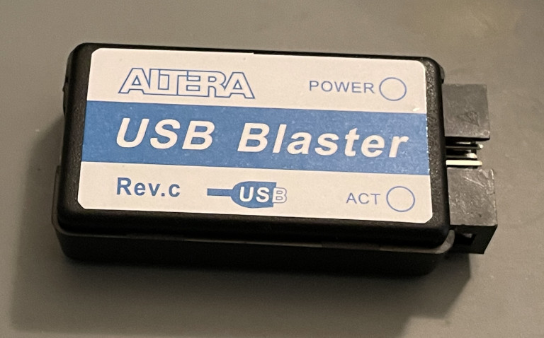
Because I don’t know how to let things go, not to mention I find this topic interesting to write about, I bought some more cheap USB Blaster clones on AliExpress. The cheaper one ($2.45) ended up being another CH552G-based one identical to the previous one I got on Amazon, right down to the Windows BSOD problem with the stock firmware. That problem is now easy to fix by reflashing it with the open-source firmware I ported.
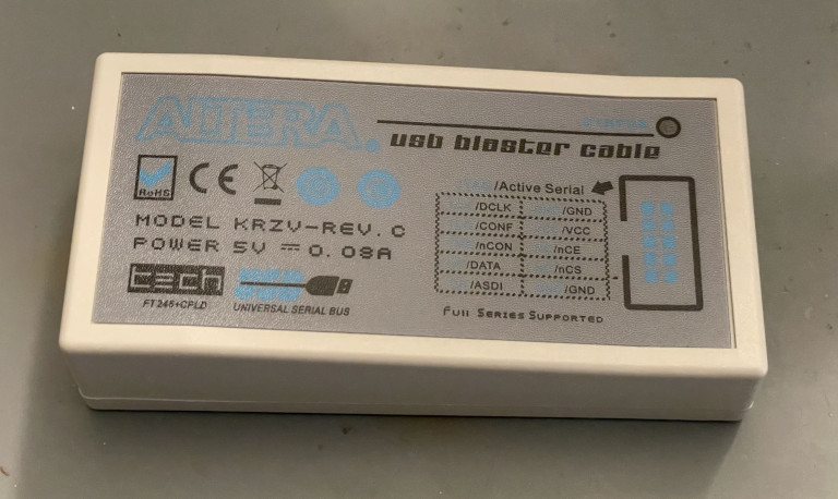
The slightly more expensive device ($9.34) was an FTDI+CPLD design with a completely different PCB and enclosure from the Waveshare one. The label on the front says it’s a model KRZV-REV. C. It still uses an Intel/Altera EPM3064ATC44-10 CPLD, exactly like the Waveshare. The pin mapping on the CPLD isn’t the same though.
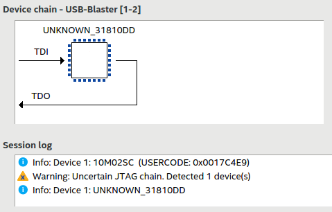
It had pretty much the same problem the Waveshare model had, though: it worked fine in Windows, but in Linux it gave me random results. It mostly didn’t work at all. I could occasionally get it to do something successfully if I tried enough times. Also, it would fail Quartus Programmer’s JTAG Chain Debugger tests, just like the Waveshare, with “Uncertain JTAG chain” warnings.
I tried soldering in a 12 MHz oscillator in place of the stock 24 MHz oscillator, but unlike the Waveshare programmer, it didn’t fix this one. That made me kind of sad, but it was also exciting. It was an opportunity to dig deeper. I was never really happy with the 12 MHz oscillator fix. Why did I have to downclock the Waveshare unit to make it work properly in Linux? It came fitted with a 25 MHz oscillator instead of 24 MHz, but it still should have worked totally fine out of the box. After all, Windows had no problems at 25 MHz.
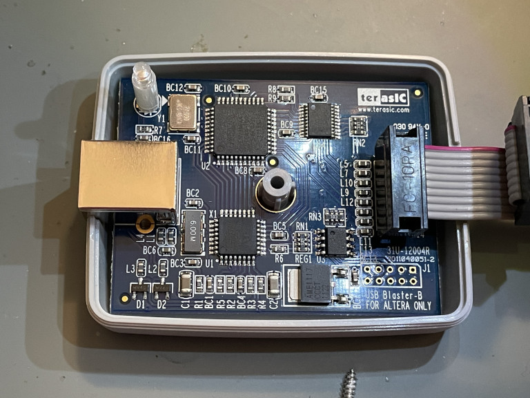
I also found a good deal on a used Terasic USB Blaster. Because why not? This is widely known to be the best USB Blaster model to use aside from Intel/Altera’s own products and is definitely reliable in Linux. I figured it would be a good baseline reference for how these units are supposed to work.
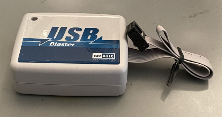
The Terasic blaster is similar to the other FT245+CPLD designs. It uses the exact same CPLD model, but the design inside does seem cleaner overall to me.
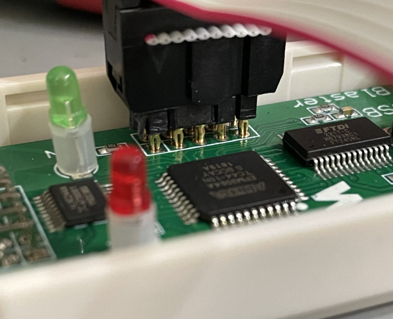
Here’s the cheap KRZV blaster, in comparison:

I looked deeper into the random failures. Since the JTAG Chain Debugger’s IDCODE iteration test seemed simple enough, I thought that would be a good place to start. I captured the USB traffic with usbmon/Wireshark while running the test with my Time Sleuth plugged in as the target. After various setup, the IDCODE iteration test seems to consist of sending this packet to the blaster repeatedly:
0000   6e 6f 6e 6f 6e 6f 6e 6f 6e 6f 6c 6d 6e 6f 6c c5
0010   a8 aa aa aa aa 6c 6d 7c 7d 7c 7c 7c 7c 7c 7c 7c
0020   7c 7c 7c 7c 7c 7c 7c 7c 7c 7c 7c 7c 7c 7c 7c 7c
0030   7c 7c 7c 7c 7c 7c 7c 7c 7c 7c 7c 7c 7c 7c 7c
Normally, when I got a good response back, it looked like this:
0000   31 60 02 02 02 02 02 02 02 02 02 02 02 02 02 02
0010   02 74 43 60 0c a8 02 02 02 03 03 02 02 02 02 02
0020   02 02 02 02 02 02 02 02 02 02 02 02 02 02 02 02
0030   02 02 02 02 02 02 02 02 02 02 02 02 02 02 02 02
When the failure occurred, I got a response like this instead:
0000   31 60 02 02 02 02 02 02 81 81 81 81 81 81 81 81
0010   81 aa a2 aa aa aa 02 02 02 03 03 02 02 02 02 02
0020   02 02 02 02 02 02 02 02 02 02 02 02 02 02 02 02
0030   02 02 02 02 02 02 02 02 02 02 02 02 02 02 02 02
Huh, that’s weird. It just started spitting out garbage 0x81 bytes. At the point where the problem began in the response packet, only the lower two bits should have been allowed to be set — it was still in bit-bang mode. It seemed like the CPLD failed to send data back to the FT245 correctly or something. Why did this not happen in Windows? Here’s the equivalent trace from Windows, starting with the packet sent out:
0000   3c 2e 2f 2e 2f 2e 2f 2e  2f 2e 2f 2e 2c 2d 2c 2e
0010   2f 2e 2c 2d 2c 2d 2c 6d  2c c4 55 55 55 55 3c 7d
0020   3c 2c 6d 2c 3c 7d 3c 2c  6d 2c 3c 7d 3c 2c 6d 2c
0030   3c 7d
And here is the response (the same every time, success):
0000 31 60 03 6e 08 8c 01 03 02 03 02 03 02 03
As you can see, jtagserver.exe on Windows does the communication completely differently. It sends out fewer total bytes, not to mention it asks for way fewer bytes to be read back in response. In comparison, jtagd on Linux seems to ask for a response for every byte it sends out.
I wasn’t really sure what to look at next, so I thought about what it would take to even consider tinkering with the CPLD design to try to figure out if I could fix it. Using my known-good CH552G-based clone (I didn’t really need the Terasic!), I was able to read out the factory-programmed CPLD bitstreams from the Waveshare and KRZV blasters. Here’s an example picture of my setup. I used a press-fit header to make temporary contact without having to solder in an actual JTAG header to the boards.
The CPLDs weren’t protected at all. This was great because it gave me the confidence I needed in order to tinker with them without worrying about permanently ruining them. If they had been locked, I could have preserved them by desoldering the original CPLDs and replacing them with spares, but I didn’t need to bother.
Reading out the original bitstreams didn’t really help me though. My understanding is that CPLDs are much easier to reverse engineer than FPGAs, but it’s still not easy. Plus, it wouldn’t give me a great functional representation of what the design was doing. I pretty quickly ruled out the possibility of reversing the original bitstreams. It would have taken way too long. In a life or death situation, I probably could have done it if I had infinite time. For the purposes of my experimentation, though, it would have been a huge waste of effort.
Instead, I scoured the internet and eventually stumbled upon the usb_jtag project, which provides some sample Altera Blaster clone implementations, including a design for an FT245+CPLD Blaster! I took a peek at the code, which someone had migrated to GitHub from the original SVN repository on SourceForge. The interesting file is jtag_logic.vhd, which implements a state machine that communicates with the FT245 and writes/reads bits on the JTAG interface.
I couldn’t resist trying this out, so I figured out the exact pinout of the generic blaster clone I was working with and built a bitstream using this design. I just had to map out all of the pins to their correct locations. I beeped them all out with my multimeter. I excitedly tried out the new bitstream on my generic blaster’s CPLD, hopeful that maybe it would work better.
Unfortunately, it acted exactly the same way. It worked great in Windows, but failed in Linux. For reference again, here is a good response during the IDCODE test:
0000   31 60 02 02 02 02 02 02 02 02 02 02 02 02 02 02
0010   02 74 43 60 0c a8 02 02 02 03 03 02 02 02 02 02
0020   02 02 02 02 02 02 02 02 02 02 02 02 02 02 02 02
0030   02 02 02 02 02 02 02 02 02 02 02 02 02 02 02 02
Here’s the bad response I got that caused the uncertain JTAG chain error:
0000   31 60 02 02 02 02 02 02 02 02 02 02 02 02 02 02
0010   02 74 43 60 0c a8 81 81 81 81 81 81 81 81 81 81
0020   81 81 81 03 81 02 02 02 02 02 02 02 02 02 02 02
0030   02 02 02 02 02 02 02 02 02 02 02 02 02 02 02 02
This failure seemed like pretty much the same exact problem I saw earlier with the stock CPLD bitstream. I should add that these failures happened in random locations. Here’s another example:
0000   31 60 02 02 02 02 02 02 02 02 02 02 02 02 02 02
0010   02 74 43 60 0c a8 02 02 02 03 03 02 81 81 81 81
0020   81 81 81 81 81 81 81 81 81 03 03 03 03 03 03 03
0030   03 03 03 03 03 03 03 03 03 03 03 03 03 03 03 03
It seemed that something was screwed up from this point on because the response ended with repeated 0x03 bytes instead of 0x02 bytes, so I guess TDO was in a different state afterward. By the way, this left me suspicious that this generic blaster from AliExpress may have been running this exact same open-source CPLD design. What are the chances that some other independent design has the same bug? I played around to try to validate that guess, but I was never able to generate a bitstream identical to my readout of the original firmware, so I can’t say for certain.
I know that FTDI’s chips have been commonly counterfeited, and that could definitely play into this problem, but I’m not sure if the fakes actually implement the FIFO mode that the USB Blasters use. I know that FTDI chips are commonly used as USB to UART adapters, so I would assume that’s the mode that would be more commonly faked. I could be wrong on that — I’d be interested in hearing others’ opinions. I assumed the FT245 was fine and went back to the drawing board to focus on understanding the open-source CPLD design.
I’m still very much a beginner with programmable logic, but I was able to figure out what the VHDL design was doing. It’s a state machine that implements the following algorithm:
- Wait for the FT245’s nRXF pin to be low, indicating it has a byte of data ready for the CPLD to read
- Drive the FT245’s nRD pin low, requesting it to put data on the D0-D7 pins
- Latch the data from the FT245
- Drive the nRD pin high to complete the read operation
- Process the received byte — this process varies because there are two modes. In summary:
- In bit bang mode, set the value of six output pins and read back the value of two input pins
- In byte mode, send 8 TCK cycles, clocking out 8 TDI bits while optionally clocking in 8 bits from TDO or ASDO
- If we are supposed to send back results to the computer, do that:
- Wait for the FT245’s nTXE to be low, indicating it’s able to receive a byte from the CPLD
- Drive the FT245’s WR pin high
- Drive data onto the D0-D7 pins
- Drive the FT245’s WR pin low, telling it to latch the data and send it back to the host machine
- Set the D0-D7 pins back to hi-Z inputs
- Lather, rinse, repeat
I handwaved away some of the more complicated stuff into the “Process the received byte” bullet point, but I didn’t want to go too far into the weeds in this post. You get the picture though. We receive a byte over USB, do what it asks us to do, and optionally send a byte back with results. The FT245 takes care of all the USB voodoo. All of the communication with the FT245 looked fine to me. It matched the timing diagrams in the datasheet.
Next, I compared this to the algorithm in the CH552G USB Blaster firmware, which I knew worked perfectly. It basically implements the exact same idea, and processes each received byte in the same way. There are a few things it handles differently. First off, it doesn’t have any of the FT245 logic because it’s directly handling the USB communication. Also, the CH552G firmware doesn’t currently support some of the lesser-used pins like ASDO/nCS/nCE, but other than that, it’s pretty much the same algorithm. One humongous difference, though, is that it’s a microcontroller performing instructions one at a time. When the CPLD writes the six output pins and reads back the two input pins in bit bang mode, it does that whole thing at the exact same time on the same clock cycle. The CH552G, on the other hand, writes the output pins one at a time and then reads TDO afterward.
I didn’t even bother looking at any signals on my oscilloscope to confirm anything. An idea jumped into my mind after I thought about this last difference. JTAG TAPs update TDO on the falling edge of TCK. It takes a brief moment for the new TDO value to become valid. For example, the Altera Cyclone IV datasheet and MAX 10 datasheet both state that TDO’s output state will become valid after a maximum of 15 nanoseconds of a TCK falling edge (tJPCO). What this means is if you toggle TCK low, you need to wait at least that long before expecting to see updated results on TDO.
The CH552G firmware was clearly respecting this delay. 15 nanoseconds is the equivalent of a clock cycle at 66.7 MHz. With the CH552G only running at 16 MHz, it was definitely waiting much longer than 15 ns between toggling TCK and reading TDO.
Just by looking at the VHDL, I could tell it was not doing any kind of delay at all. This would be impossible to see on the oscilloscope — the scope has no idea about when a receiver is sampling a signal. You just have to look at and think about the design. This is inside of a process that runs once per main clock cycle (24 or 25 MHz):
IF state = bits_set_pins_from_data THEN
	B_TCK <= ioshifter(0);
	B_TMS <= ioshifter(1);
	B_NCE <= ioshifter(2);
	B_NCS <= ioshifter(3);
	B_TDI <= ioshifter(4);
	B_OE  <= ioshifter(5);
	ioshifter <= "000000" & B_ASDO & B_TDO;
END IF;
If you’re a software person like me, you might think that these statements look like they happen in sequence, but they don’t. In this state, all six output pins and both input pins are being written and read simultaneously. This immediately jumped out to me as a big difference between the known-working CH552G and the open-source CPLD design that I was testing. The CPLD logic wasn’t waiting for the results of a TCK toggle to take effect before reading back the data on TDO and ASDO.
I still wasn’t convinced this was actually a problem though. Why did it work fine in Windows? Also, would this difference really explain the junk 0x81 bytes? That didn’t seem right. I just ignored those questions for a moment and tried adding a delay. What was the worst that could happen? It wouldn’t work?
Like I said earlier, I’m pretty green when it comes to programmable logic. I’m not sure I could have come up with this entire state machine on my own from scratch. I’m just not at that skill level yet. It’s a lot simpler to modify an existing design though! That’s what I did. I changed the bits_set_pins_from_data state to only write the outputs, and added a new subsequent state that would read back the inputs:
IF state = bits_set_pins_from_data THEN
	B_TCK <= ioshifter(0);
	B_TMS <= ioshifter(1);
	B_NCE <= ioshifter(2);
	B_NCS <= ioshifter(3);
	B_TDI <= ioshifter(4);
	B_OE  <= ioshifter(5);
END IF;

IF state = bits_read_from_pins_and_wait_for_nTXE_low THEN
	ioshifter <= "000000" & B_ASDO & B_TDO;
END IF;
The great part is that inserting this new state didn’t actually slow anything down. Prior to my change, the state machine was jumping to a different state (wait_for_nTXE_low) where it would sit for at least one clock cycle anyway. My tweak to the state machine simply made it so the readback happened during that otherwise empty clock cycle instead.
With this change implemented in the VHDL design, I generated a new bitstream and wrote it into my generic KRZV FT245+CPLD blaster. It still had the stock 24 MHz oscillator on it. Then I anxiously tried using it to program one of my Time Sleuth devices I had been testing with.
It worked! I tried multiple times in Linux and it was now behaving rock solid. The IDCODE test ran forever without any problems. I worried that I could have broken Windows compatibility in the process of fixing Linux, but it still worked fine in Windows too.
Here are examples of a successful IDCODE iteration test response in Linux before and after my change:
Before:
0000   31 60 02 02 02 02 02 02 02 02 02 02 02 02 02 02
0010   02 74 43 60 0c a8 02 02 02 03 03 02 02 02 02 02
0020   02 02 02 02 02 02 02 02 02 02 02 02 02 02 02 02
0030   02 02 02 02 02 02 02 02 02 02 02 02 02 02 02 02
After:
0000   31 60 02 02 02 02 02 02 02 02 02 02 02 02 02 02
0010   02 74 43 60 0c a8 02 02 03 03 02 02 02 02 02 02
0020   02 02 02 02 02 02 02 02 02 02 02 02 02 02 02 02
0030   02 02 02 02 02 02 02 02 02 02 02 02 02 02 02 02
Notice how the two 0x03 response bytes I bolded are now coming in one byte sooner? This is a good example of how my tweak made a difference in the response data — it sees changes to the TDO state immediately now.
For comparison, here is how the Terasic programmer replies every time:
0000   31 60 02 02 03 03 03 03 03 03 03 03 03 03 03 03
0010   03 77 43 60 0c a8 02 02 03 03 02 02 02 02 02 02
0020   02 02 02 02 02 02 02 02 02 02 02 02 02 02 02 02
0030   02 02 02 02 02 02 02 02 02 02 02 02 02 02 02 02
The Terasic readback is not exactly the same as the open-source design’s readback, which weirds me out a bit. Why is TDO changing near the beginning? It seems to be irrelevant to actual functionality though. They both work fine. I don’t have a great explanation for that difference, but I do want to point out that the two 0x03 bytes that ended up being shifted with my new design are in the exact same location on the Terasic readback. This is further confirmation in my mind that my fix is “correct” and the intended behavior of the USB Blaster is to read back the TDO state after any output changes have been given a chance to do their thing. It makes sense.
If I’m being 100% honest, even today I’m still not sure that this fix explains why I’m no longer seeing the 0x81 problem I was originally seeing. Obviously it’s protecting against a potential timing violation on readbacks, but why would delaying the readback of TDO completely eliminate a problem that causes a random sequence of bytes to be returned as 0x81? 0x81 has the highest bit set, and shouldn’t even be possible to be returned by that part of the state machine:
ioshifter <= "000000" & B_ASDO & B_TDO;
TDO changes would only affect the lowest bit. I’m wondering if there is another unrelated issue in the design that my change is somehow preventing from happening.
Even if I didn’t fully understand the fix, I was super, super excited about this. Would this also fix the Waveshare blaster from my earlier post? I soldered the original 25 MHz stock oscillator back onto the Waveshare USB Blaster, reverting it back to flaky Linux behavior. I then re-confirmed that it was still broken in Linux with its original CPLD bitstream. I figured out all of its pin mappings and finally was able to try my patched state machine on it.
It also worked perfectly in both Linux and Windows!
Boom. That was the problem, or at least one problem. The CPLD was reading the input pins too quickly after toggling TCK. I don’t know for sure why this fix isn’t needed in Windows. Maybe Intel/Altera’s JTAG server works differently in Windows and only looks at the readback on the next clock cycle, when it knows that TCK is not doing a falling edge at the same time. That’s my current guess as to why Windows always worked. I think it makes sense — I definitely observed significant differences in the USB traffic between Windows and Linux.
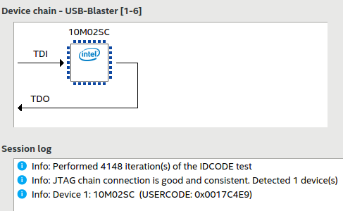
With this improved open-source CPLD design, both of my cheap FT245+CPLD-based USB Blaster clones now work perfectly in Windows and Linux with their stock 24 or 25 MHz oscillators and don’t fail any of the JTAG chain tests:
To be clear, I don’t know for sure if this is also the actual flaw that caused what I observed in the original Waveshare and KRZV CPLD implementations. I probably won’t ever know, because their designs are closed source. I’m pretty suspicious about it though, especially the KRZV one. It experienced the exact same problem in Linux that I saw with this open-source design until I tweaked it to read the inputs one clock cycle later.
One big question remains: why did my first fix of slowing down the clock on the Waveshare blaster’s original CPLD design actually work? In my mind, a slower clock speed doesn’t change the fact that TDO was being sampled really close to TCK changes. This leads me to think that the actual problem in the original Waveshare CPLD design is something completely different from the problem I tracked down in the open-source design. I’ve confirmed that with the original Waveshare bitstream, I wasn’t seeing the weird 0x81 junk bytes in bit bang mode. Instead, I was seeing a few corrupted bytes returned during byte mode. My guess is there’s some kind of a timing issue in Waveshare’s implementation of byte mode that only affects Linux for a different reason. Either way, the open-source bitstream fixes it!
I have uploaded my fixed version of the usb_jtag design to GitHub. I built the final bitstreams for the Waveshare and KRZV devices with Quartus II 13.0sp1 Web Edition. Unfortunately, you need a working USB Blaster in order to reflash the CPLD, so I’m not sure if this is really going to be practically useful for anybody at all. It was really fun figuring out the problem though, so why not share it with the rest of the world?
Here are a few more random notes I’d like to share about this whole debugging process and figuring out what was wrong with these USB Blasters:
- At one point, I was super frustrated because the generic KRZV blaster was identifying itself as a “USB-Blaster variant” (as opposed to a “USB-Blaster”) in the Quartus Programming software and wouldn’t work regardless of which bitstream I was running on it. I eventually realized that I was using a random USB A-to-B cable I had sitting around, and the cable was the problem. The cable that was originally supplied with the programmer worked fine. Strangely, the problematic cable worked fine with the Terasic blaster, so there was something about that cable that just didn’t get along with the cheap programmer. Another point in favor of Terasic.
- I also experienced a really weird unrelated problem in Quartus Programmer 18.1 in Linux while I was testing things on one of my computers. I could see corrupted outgoing USB traffic in my Wireshark capture — before the FT245 or CPLD were even involved in the equation. This problem affected all of my blasters, not just the CPLD+FT245 ones. Strangely enough, I believe jtagd from that version has some kind of weird random buffer corruption bug. This fascinating post on Intel’s forums mentioned that the corruption behavior changed based on the length of parameters being passed to jtagd. For example, launching jtagd with a seemingly garbage command line of
jtagd --user-start --config hhhhhhhhhhhhhhhhhhhhhhhhhhhhhhhworked, but passing a different length like “hhhhh” didn’t work. I actually replicated this workaround. A length of 24 h characters worked, but different lengths would result in corruption in the outgoing USB traffic. I haven’t been able to reproduce this problem on newer versions of Quartus Programmer. It also doesn’t seem to affect all of my computers. I’d highly recommend avoiding version 18.1 in Linux if you don’t have to use it. I briefly tried to look further into what was going on, but even I couldn’t convince myself to dive headfirst into that rabbit hole. - Running jtagd manually from the command line can be useful. It even has some undocumented options like
--debugand--foregroundwhich are useful for seeing what’s going on. This helped reveal to me that I should install libudev0 (sudo apt install libudev0) for better hotplug support. Without it installed, it printed this error: “No USB device change detection because libudev.so.0 not found“. - I still sometimes notice a long (~30 second) delay the first time I try to do a JTAG operation in Linux after plugging in any of my CPLD-based USB Blasters. It doesn’t happen every time, but when it does, it seems like jtagd is hung up waiting to receive a byte, which never happens, so it times out and tries again. It works fine after that. I have also observed this problem several times with the unmodified Terasic USB Blaster, so I’m not convinced this issue has anything to do with my fixed CPLD design. I’ve never seen it happen in Windows.
- Altera’s Windows JTAG server sends a big string of 64 bytes of 0x00 as the first packet when communicating with a USB blaster. Comments in the open-source CPLD design theorize that this is to force the CPLD to a known state at startup. That makes sense. For some reason, jtagd on Linux sends 64 bytes of 0x1E instead. It probably has the exact same effect, but I found it interesting that it was different. It seems like the Windows and Linux JTAG servers may not be sharing the same underlying codebase, which is surprising to me.
- I mentioned this earlier, but I still see a few minor differences in the Wireshark trace between the Terasic and the other blasters while doing something as simple as running the JTAG chain test. Clearly the Terasic design is implemented differently. Either way, they all work!
The crazy thing about all of this is that the CH552G-based programmer running my patched firmware, which you can buy on AliExpress for less than $3, seems to be one of the more reliable devices as soon as you put working firmware onto it. An added bonus is that you can update its firmware without owning another external programmer. It doesn’t seem to have the greatest circuitry inside though.
Just to hammer home this point that I’ve already mentioned, I don’t know if the fixes I described in this post are actually going to be useful for many people since you need a programmer in order to install the fixed design. It’s a bit of a chicken-and-egg problem. I’m hoping that maybe Waveshare and the generic AliExpress sellers will see this post and fix their CPLD designs going forward. It’s very easy to test the reliability of these programmers in Linux using Quartus Programmer’s built-in JTAG testing functionality.
Regardless of the practicality of this fix (or lack thereof), it feels really good to not have that 12 MHz oscillator on my Waveshare programmer anymore! That hack really bugged me, probably way more than it should have. Don’t get me wrong — I was very proud of myself for figuring out how to get it working in my last post about these USB Blaster clones. This new solution that allows me to run it at 25 MHz seems so much more elegant though!
I hope this little adventure was entertaining for someone out there. The bottom line is, it seems that a lot of these cheap clone devices are only tested in Windows. Linux users, caveat emptor!


Here’s an interesting twist to this story. This morning, I decided to throw together my own cheap USB Blaster using stuff I had laying around: an FT2232H dev board from eBay and a Cyclone IV FPGA dev board from AliExpress. I just ported over the same open-source state machine but ran it on this FPGA board instead of a CPLD. I flashed the FT2232H with an EEPROM configuration that makes it appear to be an Altera Blaster and forces channel A to be in FT245 FIFO mode.
The Cyclone IV dev board has a 50 MHz crystal so I added a simple clock enable (divided by 2) to the VHDL design so the effective clock is 25 MHz, similar to the Waveshare.
Even without my read timing patch that fixed the open-source design on the CPLDs, this cobbled-together mess works 100% perfectly with the Cyclone IV FPGA. My patch doesn’t hurt anything, and again makes the output closer to the results I see from the Terasic (the location of the two 0x03 bytes matches the Terasic), but even without my patch it works flawlessly. Because it’s an FT2232 that supports high-speed USB, each packet is now around 512 bytes instead of 64 (padded with 0x7c on the output and 0x02 on the input), but that’s the only difference I’ve seen. It seems much snappier because of the high-speed USB, I might add!
Now I’m really puzzled! Should I be blaming the FT245? Is there some funkiness going on with the CPLD versus the FPGA? Why did tweaking the design make the problem go away on the CPLD, but it doesn’t matter either way on the FPGA?
Thank you for the write-up. It’s fascinating to delve in the details of the cheap, and not-so-cheap adapters! For reference, an original Altera USB Blaster Rev. C manufactured near the end of 2014 uses EPM7064AE with 24MHz crystal, FT245BL with 6MHz crystal, and the main difference, it has 1xLVC244 and 2xMAX3378 for level shifting. You may also like to have a look at LibXsvf for similar programmer implementations.
Hi Steve, thanks for your comment! That’s good to know. It seems like Altera’s original USB Blaster probably has the nicest circuitry of all of them based on what you described. Thanks for the pointer to LibXsvf!
Very entertaining. Re The mysterious 30 second delay, the jtag server stops when idle or corrupt. The programmer and debug software automatically relaunch if it isn’t there. Causes a little delay. That’s probably what’s happening there.
Hi Somebody, yeah — there’s definitely something going on with launching and relaunching the JTAG server. I didn’t mention it in the post, but if I stop it and manually start it again, I can try again and it always works instantly. I think there’s some subtle issue with how it first launches sometimes. I’m not sure.
Hi, in github @thisiseth made a usb-blaster with raspberry pi pico can you try this it seems a good alternative as cheap blaster.
Thanks.
https://github.com/thisiseth/pico-usb-blaster
Interesting Muhammet! I agree, this looks like a solid option especially if you already have a Pico sitting around.
Tried your waveshare.pof from 1.0.0 release and having constant fail when programming POF to MAX10 at 17% (quartus std 23.1 under Linux). Detect chain & programming SOF is working always. The hw is unmodified waveshare v2 with 25MHz crystall
Hi Harbour,
Have you tried an older version of Quartus? I have seen similar problems with 23.1 and MAX10 even with legit blasters. I think it’s a Quartus bug. 20.1.1 works well.
The same quartus version is working ok with CH552G-based USB blaster using exact the same setup (laptop, cables, devboard)
Very interesting! I’d still recommend trying the older 20.1.1 version as a test, just because I know there are MAX10 compatibility issues with newer Quartus versions. I’m surprised you were able to get it to work with the CH552G-based blaster.
You were right – v20.1.1 works with waveshare.pof and 25MHz crystall.
But 23.1 works really stable with CH552G using v1.1.0 usb_blaster.bin !
That’s really interesting that it still works with the CH552G version! J.Bilander posted a comment on my first USB blaster post with a link to an Intel support article about one incompatibility with a MAX10 model and POF files:
https://www.intel.com/content/www/us/en/support/programmable/articles/000092639.html
It states the bug was fixed in 24.1 Standard and 24.3 Pro. It might be worth trying the newer version to see if the bug they fixed is what you are running into.
I don’t think there’s anything wrong with the CPLD design that causes this, because I also saw the same problem with the Terasic USB blaster which is an officially supported one.
I’ve tried with 24.3 Pro and it works with both as with waveshare.pof at 25MHz as with CH552G using v1.1.0 usb_blaster.bin. But I’m having MAX10 and 24.3 Pro do not support it except programming. The latest std version is 23.1 not 24.1 – poor intel has typo at its own page.