I recently had the opportunity to get a Freescale KwikStik Kinetis K40 Cortex-M4 development board (thanks, Newark/Farnell!). I’ve been using the Cortex-M3, so I had been very excited to test out the Cortex-M4. Plus, I have also been anxious to evaluate Freescale’s ARM offerings, so this was the perfect board for that. Sadly, the Cortex-M4 included in the K40X256VLQ100 chip used on the KwikStik does not have the optional floating-point unit, so I wasn’t able to do any performance tests as far as that is concerned.
Anyway, I thought I’d share my experience with the board, so here goes nothing!
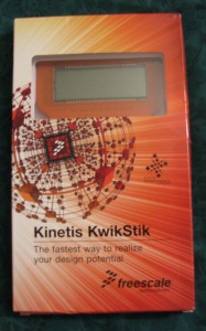
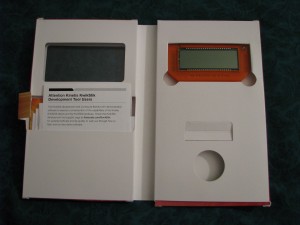
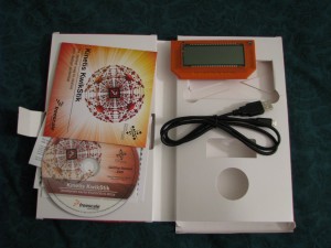
It came packaged in a nifty box that opens up to reveal two sides — one with some documentation and a getting started DVD, the other with the Kinetis in its awesome cover and a USB A-to-micro-B cable:
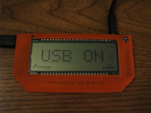
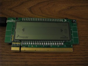
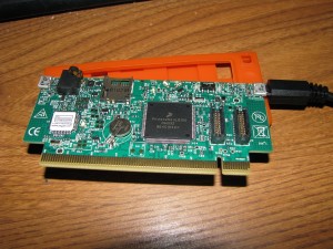
Here is the KwikStik, powered up in all its orange glory:
And here it is outside of its case:
The DVD contains various PDF datasheets for the Kinetis microcontrollers, evaluation and code-limited versions of several compilers, and Freescale’s MQX RTOS.
Freescale put a ton of interesting things on the KwikStik to play around with:
- LCD display
- 3.5 mm audio output jack
- Microphone
- Buzzer
- Onboard USB J-Link programmer for flashing the chip (and to use the board as a programmer for other boards)
- USB OTG/host/device port for applications
- Infrared transmitter/receiver
- microSD card slot (doesn’t totally work in the revision I received — see below)
- Six capacitive touch buttons
- Rechargeable MgLi (manganese lithium) coin cell battery
So without further adieu, let’s get started with the fun stuff!
When you power the board up with the default firmware by plugging into either of the two USB ports, a menu comes up with three options, navigable with the capacitive touch buttons. The options are: sound recorder, remote control, and USB joystick.
The sound recorder will record two seconds of audio with the built-in microphone and play the recorded sound back through the 3.5 mm jack. The remote control feature is meant for controlling a Sony TV, and the USB joystick will let you use some of the capacitive touch buttons as a simple HID joystick on a computer.
Unfortunately, I couldn’t get the HID joystick demo to work — it was recognized on the computer as a gamepad, but the buttons wouldn’t register any presses in the Windows 7 game controller settings dialog. I also couldn’t test the Sony TV controller since I have a Vizio TV. The sound recorder works fine though!
The default firmware doesn’t really matter much, though — the fun part is making your own programs to do stuff! To start out, I downloaded CodeWarrior Development Studio for Microcontrollers (Special Edition with 128K code size limit). I had to download it since it didn’t come on the DVD. Installing it was a bit of a pain because I later found out that putting it in the default C:\Program Files (x86) directory will cause problems later on when trying to update it, so I had to uninstall it and put it in a standard unprotected location where administrator access isn’t needed to modify files. Despite that annoyance, I like it because it’s based on Eclipse and I’m used to Eclipse. I also tried IAR, but I didn’t like the user interface (and couldn’t get it to work with the demo firmware anyway). I also downloaded the Segger J-Link software — Segger’s site seemed to imply that my DVD should have come with it, but I couldn’t find it as an option to install in the Flash interface. Luckily, Segger still lets me download it as long as I agree not to use it with illegal cloned boards. So I got that all ironed out!
Despite not caring too much about the default firmware, the first thing I did was download the factory image off the device, just in case. After installing the Segger software, I used JLink.exe to read the flash contents after using JMem.exe to determine where the flashed image ended (where a bunch of endless 0xFFs began). It turns out the firmware binary is 0xD004 bytes long, so I used these commands in JLink.exe:
h
savebin C:\Path\To\DefaultFirmware.bin, 0x0, 0xD004
The “h” command halts the CPU, and the “savebin” command will save 0xD004 bytes of data starting at address 0 to DefaultFirmware.bin, so I can always restore the board back to the exact way I got it. Yeah, I’m paranoid like that. It’s always the first thing I do when I get a microcontroller evaluation board. The way I see it, I’m going to need to know how to use the flashing/debugging tools anyway, so it’s not a waste of time to do that first!
Next, I decided to try to compile Freescale’s example firmware to see if maybe they had worked out some of the kinks in the HID joystick demo. This required updating CodeWarrior to the latest version and installing the latest version of Freescale’s MQX RTOS, which the demo uses. Finally, after trying to compile the example firmware, I ran into some errors because there were a couple of hardcoded “C:\Program Files” paths which I had to change. After all that mumbo jumbo, I was finally able to compile their example firmware which is available for download on the KwikStik page on their website.
Programming the device from inside CodeWarrior worked fine, and once that was done, I ran the demo — they actually had replaced the HID demo with a USB mouse demo, which does work (it lets me left click and right click). They had also fixed a bug that caused the remote control app’s exit button to not work, and they added a Tetris clone game demo.
OK, so at this point I finally had an environment ready for doing some real development! I didn’t really feel like learning how to use Freescale’s RTOS yet, so I just made a simple bare metal demo app to turn on all the LCD’s segments in succession, then turn them off in succession, endlessly.
CodeWarrior comes with some pretty interesting features — the microcontroller appears as a picture in CodeWarrior, and the picture contains a bunch of blocks for all the peripherals built in, including the CPU itself. You can click on them to set up options (such as clocking for the CPU) and it will generate initialization code for you. It made it pretty easy to make a quick app. I borrowed some of the code from the KwikStik demo application for the LCD to understand the options Freescale used for setting it up, and it pretty much worked right out of the box. It turned out that the LCD was visibly flickering in my app, and it was because I had to change the IRCLK source to be the fast internal reference clock (2 MHz) instead of the default slow internal reference clock (32.768 KHz) — it looks like the SLCD’s initialization was using the IRCLK and the default setting was not fast enough, so I saw flickering. With that out of the way, my program worked like a charm!
After all the initialization is complete, here’s the simple main loop code:
int x;
int y;
volatile int c;

for (;;)
{
    for (x = 1; x < 40; x++)
    {
        for (y = 0; y < 8; y++)
        {
            // Turn on the segments one at a time...
            LCD_WF8B(x) |= (1 << y);

            // Wait a bit?
            c = 0x20000;
            while (c--);
        }
    }

    for (x = 1; x < 40; x++)
    {
        for (y = 0; y < 8; y++)
        {
            // Turn off the segments one at a time...
            LCD_WF8B(x) &= ~(1 << y);

            // Wait a bit?
            c = 0x20000;
            while (c--);
        }
    }
}
I like the SLCD peripheral! It makes it easy to turn segments on or off by changing a single bit, and then you’re done. The SLCD peripheral uses up to 8 pins as backplane pins, and the other 40 pins can be used to control 40 segments per backplane. It is very quickly switching between the eight backplanes and turning the segments on and off as necessary. This all happens so fast that you have no idea that the LCD segments are being turned on and off (well, unless you accidentally set the clock rate too low like I did!). With 8 backplane pins and 40 segment pins, you can control up to 320 LCD segments with this peripheral. It would be a big pain in the rear end to implement the LCD refreshing I just described manually, and the peripheral makes it so easy — just set the bit for the segment you want to turn on, and you’re done!
The next thing I should do is get rid of the ugly busy waiting that I have for delays right now, and switch over to using a timer, which would be pretty easy to do.
So yeah, once you get down to making your own stuff, it’s a cool little board with tons of possibilities for interesting applications!
Now, remember how I said the SD card slot doesn’t totally work? Well, it turns out that in board revisions earlier than revision 5 (I received revision 4), Freescale accidentally connected the SD card socket’s data pins to the wrong pins on the microcontroller! It essentially makes the microSD card slot useless because you can’t use the Kinetis’s built-in SDHC controller peripheral for accessing the SD card. You could bit-bang it yourself, but that will have a (very negative) performance impact. Maybe I can hack the board with some cut traces and wires to connect the SD card socket’s pins to the correct microcontroller pins — who knows? Maybe I’ll do THAT as a fun project soon! If I do, I’ll be sure to post about it here!
So, in conclusion, I’m happy with the board, although it seems like Freescale made a really boneheaded mistake (the SD card wiring problem is inexcusable, especially given that it was still present in revision 4 of the board!). Regardless of that, though, I’d still definitely recommend it as a platform for learning about microcontrollers, simply because of all the awesome stuff it has built-in aside from the microSD slot. And seriously, a 100 MHz processor in a microcontroller? I know the Cortex-M3s were up there in clock speed too, but still–what’s the world coming to? With all of that processing power combined with the wide range of peripherals, it provides plenty of awesome opportunities to learn about microcontroller programming. The included orange protective jacket is a nice touch, too!
You can purchase the Kinetis KwikStik from Newark.
Until next time, see ya later!


Interesting, I didn’t realize CodeWarrior made mcu development tools.
What actually is the difference between the M3 and M4? Is it just the same thing at higher speeds and with more memory?
Hey Steve,
Yeah, after Motorola bought Metrowerks they turned it into an IDE for their processors/microcontrollers. I think you’re pretty much spot-on as far as the difference between the M3 and the M4. I know that the M4 is 100% backwards-compatible with M3 software, and the M4 adds some (optional?) DSP and floating point instructions. I know for a fact that the floating point is optional, because the chip used in the KwikStik doesn’t have it.
Thanks!! I am a newbie and was struggling to compile the demo package, since there was no project file. I installed IAR, but without a .eww file, I was lost. Can you please explain the command to use to restore the card with the original firmware, please.
Prakash
Hi Prakash,
I never figured out how to compile the demo project with IAR. Once I realized that CodeWarrior was Eclipse-based, I switched over to it because I like Eclipse.
However, there is a .eww file included with the download of Freescale’s MQX RTOS — it’s in <MQX Directory>/demo/Kwikstik_Demo/iar
You probably also will have to install the MQX 3.7 KwikStik patch available at the bottom of this page.
Thanks!! I am a newbie and was struggling to compile the demo package, since there was no project file. I installed IAR, but without a .eww file, I was lost. Can you please explain the command to use to restore the card with the original firmware, please.
Also I could not locate where the originalk firmware with the sound recorder, fretris and other initial files are located, can you please tell me where you found them?
Prakash
Hi Prakash,
Here’s the deal — my version of the KwikStik came with an original firmware of: sound recorder, sony TV remote, and USB gamepad. I was never able to find a way to restore that original firmware. Instead, the MQX RTOS included a new version of the firmware that has a sound recorder, Sony remote, USB mouse, and Fretris. You should be able to restore that version of the firmware by compiling it with IAR and downloading it to the KwikStik from within IAR.
I was never able to find an original firmware binary, but you should be able to compile it. Download and install the MQX RTOS 3.7 from here, along with the Kinetis KwikStik patch. You might also be able to get away with installing version 3.8 instead. Once you install those, the demo project is included in the directory I mentioned in my last comment.
Only that area of the screen is available?
Alguém sabe como utilizar o receptor de infravermelho do kwikstik? Como eu faço para receber um comando de um controle remoto e armazenar essa informação?
Does anyone know how to use infrared receiver kwikstik? How do I receive the command from a remote control and store this information?