In my last post in the series about microcontroller programming for normal programmers, I talked a little bit about general purpose I/O. I’d like to expand on this topic today by talking about inputs, outputs, pull-ups, and pull-downs. As a summary, a GPIO pin on a microcontroller can be set up to be an input or an output, and if it is set as an input, there are various options you can set for how the input works. This is the first step toward getting the microcontroller to actually do something. I’ll go into more detail now.
When I was talking about a hypothetical “light-emitting diode” peripheral last time, I was basically describing the output functionality of a GPIO port. If you set a GPIO pin as an output, you can control whether its output is a 1 or 0. What does this 1 or 0 mean? Well, a microcontroller generally operates at a voltage, such as 5 volts or 3.3 volts. I’ve been playing with various incarnations of the ARM Cortex-M3, and they have all been 3.3V, while older microcontrollers like the Freescale 68HC11 run at 5V. I’ve also seen some new Cortex-M3s that operate at 5V, but let’s just assume for today that we’re working at 3.3V. Generally, this means your GPIO pins also operate at that same voltage. Basically, a 1 is represented by 3.3V (VCC), and a 0 is represented by 0V, or ground (GND). Since the LED was connected to one of the microcontroller’s pins, we could turn it on or off by setting the GPIO pin’s output value to 0 or 1.
If you understand everything I just wrote, congratulations. You understand outputs.
Inputs are different. You have something else hooked up to your GPIO pin, but you’re not controlling it. Instead, you’re determining whether it’s currently “showing” a 1 or 0 value to you. What kind of use would this have? Well, the easiest example is probably a push button. If you want to determine whether a push button is “pushed” or “released”, you could hook it up to a GPIO pin so that you can read whether you’re seeing a 1 or 0. However, because of how electricity works, it’s going to get slightly complicated, so bear with me.
If you’re not familiar with how buttons work, here’s a quick explanation. Buttons have two terminals on them. When the button is pushed, the terminals are connected together internally, creating a “closed circuit”, allowing electricity to flow through them. If the button is not being pushed, the terminals are not connected together, so electricity is not allowed to flow between them. Got it? Good!
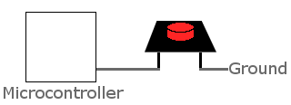
When you wire a button to a microcontroller’s GPIO pin, you hook one of the button’s terminals to the pin, and you hook the other terminal to either ground or VCC (3.3V in our case). But you’re not done yet! Let’s assume we wired the button to GND (0V). See the picture above. So when the button is pushed, the circuit will close, and thus, it will be as if the microcontroller pin was connected directly to ground. If you read the port pin at this time, you will get a 0. However, if the button is not pressed, the circuit does not close. In that case, as far as the microcontroller pin is concerned, it’s not connected to anything else in the circuit. It’s floating. This means the value you read from the pin will be unpredictable.
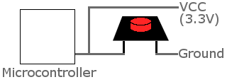
So…we need a way to make it so the pin thinks it has 3.3V connected when the button is not pressed. That way, it would read a 1 if the button is released, and a 0 if it’s pressed. How can we do that? Well, we need to hook it to VCC as well. So we leave the existing connection to the button in place, but also add another connection so the port pin is always connected to VCC. See the picture below.
Let’s think about what this will do. When the button is released, the port pin is connected directly to VCC, reading a 1. But if it’s set up this way and you press the button, the port pin will still be directly connected to VCC, but closing the button’s circuit will also directly connect it to GND at the same time. In other words, you will have VCC and GND directly connected together with no resistance in between (the button itself doesn’t count as resistance — it’s just like a wire). This is commonly referred to as a short circuit, and it will cause things to get hot very quickly. You will probably burn up the circuit board and the microcontroller, creating some magic smoke in the process.
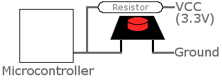
Now what? How can we safely stay hooked to both VCC and GND simultaneously? We need a resistor. Instead of connecting the GPIO pin directly to VCC, put a resistor between the pin and VCC. See below.
When the button is released, the pin will no longer be directly connected to VCC, but it will be connected to VCC through a resistor, which is perfectly OK, and will still cause the voltage on the pin to be 3.3V, or 1. When the button is pressed, the pin will be connected to VCC through the resistor, and also directly to GND through the button. If you think about it, this also means VCC will be connected to GND through a resistor. Since there’s a resistor in between, you won’t get any smoke. It’s no longer a short circuit. Now let’s look at it from the point of view of the port pin–it’s still simultaneously connected to GND and VCC. Since it’s connected to VCC through a resistor, and directly to GND, GND will “win”. VCC is trying to pull the port pin’s value up to a 1, but with the resistor in between, it’s a very weak connection compared to the pin’s connection to GND, so GND keeps the port pin pulled down to 0.
I know this may be kind of confusing, especially if you have no experience with electricity. I hope the pictures make sense. I didn’t understand this concept at first, but it’s pretty important. You need to understand it so that you can understand pull-up and pull-down resistors.
Basically, here’s the purpose of pull-up and pull-down resistors. When nothing is hooked up to a pin, a pull-up or pull-down resistor will give that pin a default value. If you have a pull-up resistor enabled, the default value will be a 1. If you have a pull-down resistor enabled, the default value will be a 0. In our example, we started out with the microcontroller only hooked to the button, which gave the input a value of 0 when the button was pressed. We then added a connection to VCC through a resistor to give the input pin a value of 1 when the button was not pressed. It turns out that what we added is called a pull-up resistor, and most microcontrollers nowadays have them built in. You just have to enable them.
So instead of having to add a resistor outside of the chip, we actually can get away with hooking the button directly to the pin as we did in the first picture, which I am showing again below.
Until we enable the internal pull-up resistor on that pin, we’ll run into the same problem I mentioned at first–when the button is not pressed, the value we read will be unpredictable, because the pin is not hooked to anything in the circuit. So if we enable the pull-up resistor, the full circuit will look just like the third picture above where we added the resistor. It’s just that the resistor connected to VCC is inside the chip, so we don’t have to bother adding it to our circuit board–we just have to tell the microcontroller to turn it on. Nice, huh?
Pull-down resistors work the same way, but they connect the pin through a resistor to ground, rather than VCC. Many microcontrollers also have pull-down resistors built in.
I’ve talked enough about the hardware side for one day, so now let’s get to the part we programmers enjoy–the software. Usually, you have a memory-mapped GPIO peripheral. Let’s assume we have a hypothetical PORTA peripheral mapped in memory to address 0x100.
PORTA is made up of four 8-bit registers:
DATAA
DDRA
PULLUPA
PULLDNA
DATAA is at 0x100, DDRA is at 0x101, PULLUPA is at 0x102, and PULLDNA is at 0x103.
I’m actually going to explain the DDR register first. DDRA stands for data direction register A. It describes whether each pin on PORTA is an output or an input pin. An input is represented by a bit being zero, and an output is represented by a bit being 1. So if DDRA was set to 0x03, then port A pins 0 and 1 are outputs, and the rest of its pins are inputs. It’s as simple as that.
If you set a pin as an output, you can change its output value by changing the appropriate bit in the DATAA register. For instance:
DATAA |= 0x01;
will set port A, pin 0 to the value “1” or “high” or “3.3V” or however you’d like to think of it.
DATAA &= ~0x02;
will set port A, pin 1 to the value “0” or “low” or “ground”.
If you read my last post about memory-mapped peripherals, this should all make sense.
On the other hand, if you set a pin as an input, you have a few more options. You can turn on the pin’s pull-up or pull-down resistor (but certainly not both at the same time–that would make no sense). You don’t have to turn on either resistor if you don’t want to. It only makes sense to enable pull-ups or pull-downs on pins set to input–the value will be ignored for outputs.
PULLUPA |= 0x04;
will turn on the pull-up resistor on port A, pin 2.
PULLDNA |= 0x08;
will turn on the pull-down resistor on port A, pin 3.
Finally, to read the input value on an input pin, you read the DATAA register. If you only care about a specific pin, you can ignore the rest of the bits using bitwise operations in C. For instance:
if (DATAA & 0x04)
The above line will be true if port A, pin 2 has an input value of 1 (in our example, that would mean the button connected to it is not being pressed)
if ((DATAA & 0x04) == 0)
The above line will be true if port A, pin 2 has an input value of 0, meaning the button is pressed.
If you try to read the input value of an output pin, it will just tell you the last value you set it to output.
Whew! You made it! That’s really all you need to know about GPIO for now. The way I described the software interface to these GPIO pins is generally exactly how it works in a real microcontroller. The registers might have slightly different names, and their organization in the memory map may be different, but that’s essentially how it goes. I did skip some more advanced stuff, but for now the other stuff is not important.
Congratulations–you’ve made your way through understanding the first built-in peripheral in a microcontroller. My next article will be an introduction to interrupts–a very important concept in microcontroller programming. The reason they are important is that they tell you that an operation has completed, or something is ready. Interrupts also took me quite a while to fully understand, but they are another important concept. If you’ve ever used signal handlers in your regular desktop programs, it’s the same kind of concept. Your program stops and another portion of code executes instead, and then your program picks up where it left off as soon as the other portion of code is done. Anyway, I won’t go into any more detail about them until my next article. See you then!


The best article that explain pull up and pull down that I never read before.
Thank you
Thank you for the kind comment! I’m glad it helped 🙂
Very nicely articulated and explained.Even a noob like me was able to understand very easily.
Thanx.
I love it , wish my teachers had explained it this way!!
Can we make this sticky in google somehow? Right on top of it? 🙂
Thank you for this write-up!
well explained sir,thank u very much….